Difference between revisions of "Dual-loop feedback position control"
| [checked revision] | [checked revision] |
| Line 4: | Line 4: | ||
A typical closed loop controller resembles the diagram below. | A typical closed loop controller resembles the diagram below. | ||
| − | + | {{picturebox|Controller general.png|350px}} | |
The closed loop system is formed by an '''actuator''', '''feedback''' and '''substraction''' (sigma): | The closed loop system is formed by an '''actuator''', '''feedback''' and '''substraction''' (sigma): | ||
| Line 13: | Line 13: | ||
In a practical case, this type of closed loop may be used for servo motor position control just by choosing appropriate components: | In a practical case, this type of closed loop may be used for servo motor position control just by choosing appropriate components: | ||
| − | + | {{picturebox|Controller position.png|350px}} | |
This kind of controller could be used to produce linear motion with appropriate mechatronics assembly such as: | This kind of controller could be used to produce linear motion with appropriate mechatronics assembly such as: | ||
| − | + | {{picturebox|Servolinearaxis.png|600px}} | |
==Linear encoder feedback== | ==Linear encoder feedback== | ||
The drawback of above position control system is the position error caused by lead screw backlash, pitch error and flex. The problem is that the error is unknown because it is not being measured or controller: | The drawback of above position control system is the position error caused by lead screw backlash, pitch error and flex. The problem is that the error is unknown because it is not being measured or controller: | ||
| − | + | {{picturebox|Controller position with error.png|500px}} | |
===Dual-loop system=== | ===Dual-loop system=== | ||
To elimiate the error of mechanics, one can add a linear encoder to read out the actual position of the axis instead of using derived value from rotary encoder behind the lead screw: | To elimiate the error of mechanics, one can add a linear encoder to read out the actual position of the axis instead of using derived value from rotary encoder behind the lead screw: | ||
| − | + | {{picturebox|Servolinearaxis dualloop.png|600px}} | |
However the problem there is that we have two separate position feedback signals: rotary and linear. One may think to replace rotary feedback with linear feedback in the original system. However, that will cause stability problems to the control loop due to backlash and flex of the mechanics. If motor is being controlled based on feedback signal with time delay (due to flex and backlash), it will easily render control loop unstable or leave user with very [[Servo stiffness|low stiffness]]. | However the problem there is that we have two separate position feedback signals: rotary and linear. One may think to replace rotary feedback with linear feedback in the original system. However, that will cause stability problems to the control loop due to backlash and flex of the mechanics. If motor is being controlled based on feedback signal with time delay (due to flex and backlash), it will easily render control loop unstable or leave user with very [[Servo stiffness|low stiffness]]. | ||
| Line 33: | Line 33: | ||
In order to achieve stiff position control it is necessary to control motor by it's local rotary encoder AND control axis position based on linear encoder. Such system can be achieved by a dual-loop feedback system: | In order to achieve stiff position control it is necessary to control motor by it's local rotary encoder AND control axis position based on linear encoder. Such system can be achieved by a dual-loop feedback system: | ||
| − | + | {{picturebox|Controller dualloop.png|750px}} | |
[[category:glossary]] | [[category:glossary]] | ||
[[category:technology]] | [[category:technology]] | ||
Revision as of 14:47, 14 August 2014
In many linear motion cases it is preferred to use linear encoder mounted directly to the axis to provide accurate position readout and to use it as feedback signal for position controller. The benefit of that is the elimiation of error sources between rotary motor and linear motion. This page explains the implementation of such system.
Contents
Background
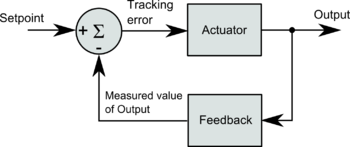
A typical closed loop controller resembles the diagram below.
The closed loop system is formed by an actuator, feedback and substraction (sigma):
- Actuator is typically a comination of amplifier (such as a P or PI or PID gain amplifier), driver (such as an adjustable current source), and transducer (such as a motor).
- Feedback is typically a feedback device that measures the system output and converts it a numeric value (such as position count).
- Substraction (sigma) part is simply a calculation for tracing error: tracking_error = setpoint - measured_value_of_output
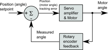
Practical position control servo axis
In a practical case, this type of closed loop may be used for servo motor position control just by choosing appropriate components:
This kind of controller could be used to produce linear motion with appropriate mechatronics assembly such as:
Linear encoder feedback
The drawback of above position control system is the position error caused by lead screw backlash, pitch error and flex. The problem is that the error is unknown because it is not being measured or controller:
Dual-loop system
To elimiate the error of mechanics, one can add a linear encoder to read out the actual position of the axis instead of using derived value from rotary encoder behind the lead screw:
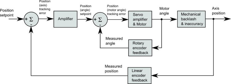
However the problem there is that we have two separate position feedback signals: rotary and linear. One may think to replace rotary feedback with linear feedback in the original system. However, that will cause stability problems to the control loop due to backlash and flex of the mechanics. If motor is being controlled based on feedback signal with time delay (due to flex and backlash), it will easily render control loop unstable or leave user with very low stiffness.
In order to achieve stiff position control it is necessary to control motor by it's local rotary encoder AND control axis position based on linear encoder. Such system can be achieved by a dual-loop feedback system:


