Dual-loop feedback position control
In many linear motion cases it is preferred to use linear encoder mounted directly to the axis to provide accurate position readout and to use it as feedback signal for position controller. The benefit of that is the elimiation of error sources between rotary motor and linear motion. This page explains the implementation of such system.
Contents
Background: traditional signel-loop feedback[edit | edit source]
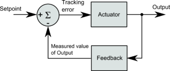
A typical closed loop controller resembles the diagram below.
The closed loop system is formed by an actuator, feedback and substraction (sigma):
- Actuator is typically a comination of amplifier (such as a P or PI or PID gain amplifier), driver (such as an adjustable current source), and transducer (such as a motor).
- Feedback is typically a feedback device that measures the system output and converts it a numeric value (such as position count).
- Substraction (sigma) part is simply a calculation for tracing error: tracking_error = setpoint - measured_value_of_output
Practical position control servo axis[edit | edit source]
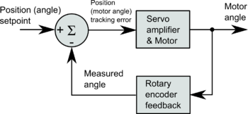
In a practical case, this type of closed loop may be used for servo motor position control just by choosing appropriate components:
This kind of controller could be used to produce linear motion with appropriate mechatronics assembly such as:
Dual-loop system: linear encoder feedback[edit | edit source]
The drawback of above position control system is the position error caused by lead screw backlash, pitch error and flex. The problem is that the error is unknown because it is not being measured or controller:
Dual-loop system[edit | edit source]
To elimiate the error of mechanics, one can add a linear encoder to read out the actual position of the axis instead of using derived value from rotary encoder behind the lead screw:
However the problem there is that we have two separate position feedback signals: rotary and linear. One may think to replace rotary feedback with linear feedback in the original system. However, that will cause stability problems to the control loop due to backlash and flex of the mechanics. If motor is being controlled based on feedback signal with time delay (due to flex and backlash), it will easily render control loop unstable or leave user with very low stiffness.
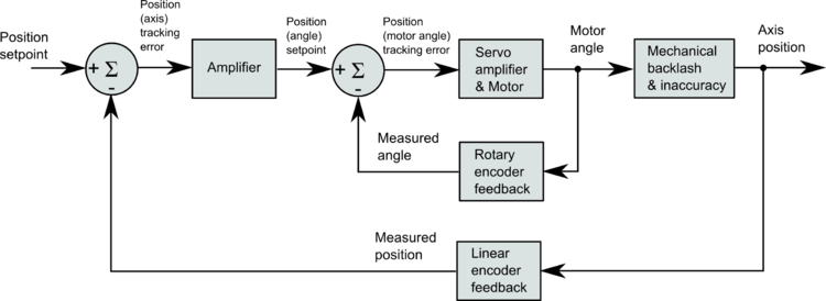
In order to achieve stiff position control it is necessary to control motor by it's local rotary encoder AND control axis position based on linear encoder. Such system can be achieved by a dual-loop feedback system:
In the system above, we have two contorl loops: inner loop (rotary encoder based) and outer loop (linear encoder based). In this system outer loop generates the setpoint for the inner loop to correct the small error produced by mechanical inaccuracies.
How to build a dual-loop system[edit | edit source]
The most common method to make a dual loop system is to connect servo motor with rotary encoder to a servo drive and tune it for velocity control mode. The linear encoder feedback should go to the controller that implements it's own position control and outputs a velocity setpoint to the servo drive.
Servo drive can be also set in position or torque mode but the simplest solution is to use velocity control mode in the inner loop.
From off-the-shelf solutions at least LinuxCNC supports dual-loop operation as the software implements a position controller with feedback input.
In no event the Product Information or parts hereof shall be regarded as guarantee of conditions or characteristics. The Product Information or any part thereof may also not be regarded as a warranty of any kind. No liability of any kind shall be assumed by Author with respect to Product Information or any use made by you thereof, nor shall Author indemnify you against or be liable for any third party claims with respect to such information or any use thereof.
As content of this Wiki may be edited by user community, Granite Devices Oy or it's affiliates do not take any responsibility of the contents of this Wiki. Use information at your own risk. However, Granite Devices staff attempts to review all changes made to this Wiki and keep information trustworthy.
Without written consent, Granite Devices' Products or Intellectual Property shall not be used in situations or installations where living beings, material property, or immaterial property could be harmed by the operation, features or failures of Product. Products may only be used in a way where hazards like moving parts, electric shock, laser radiation, or fire can't be realized even if the content of this Wiki would suggest otherwise.


