Difference between revisions of "IONI hardware revisions"
From Granite Devices Knowledge Wiki
| [checked revision] | [checked revision] |
(Tag: VisualEditor) |
(add see also) (Tag: VisualEditor) |
||
| (13 intermediate revisions by the same user not shown) | |||
| Line 1: | Line 1: | ||
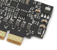
| + | [[File:Ioni pcb revision id.jpg|thumb|PCB version print on the corner. This is from PCB026.|240x240px]] | ||
List [[IONI]] drive hardware revisions and changes. | List [[IONI]] drive hardware revisions and changes. | ||
| Line 4: | Line 5: | ||
|- | |- | ||
! Release date !! Models !! PCB version | ! Release date !! Models !! PCB version | ||
| − | !Component configuration!! Changes | + | !Component configuration!! Changes & Impact |
| + | !How to identify | ||
|- | |- | ||
| − | | 2015 || IONI, IONI Pro, IONI Pro HC || V26 | + | | 5.2015 || IONI, IONI Pro, IONI Pro HC || V26 |
|Initial version|| Initial release | |Initial version|| Initial release | ||
| + | | | ||
| + | * Component RN5 has value 221 | ||
| + | * On corner of PCB behind LEDs is small print reading PCB026 | ||
|- | |- | ||
| Line 16: | Line 21: | ||
** No practical effect for end user | ** No practical effect for end user | ||
* Changed GPI1,2,3 series resistors from 220 ohm to 68 ohm | * Changed GPI1,2,3 series resistors from 220 ohm to 68 ohm | ||
| + | ** Improve clock signal strength with BiSS and SSI encoders | ||
| + | | | ||
| + | * Component RN5 has value 680 | ||
| + | * On corner of PCB behind LEDs is small print reading PCB026 | ||
|- | |- | ||
| 1.2017 | | 1.2017 | ||
| Line 21: | Line 30: | ||
|V6|| | |V6|| | ||
* Changed GPI1,2,3 series resistors from 220 ohm to 68 ohm | * Changed GPI1,2,3 series resistors from 220 ohm to 68 ohm | ||
| + | ** Improve clock signal strength with BiSS and SSI encoders | ||
| + | | | ||
| + | * Component RN5 has value 680 | ||
| + | * On corner of PCB behind LEDs is small print reading PCB026 | ||
|- | |- | ||
| 1.2017 || IONI, IONI Pro, IONI Pro HC || V29 | | 1.2017 || IONI, IONI Pro, IONI Pro HC || V29 | ||
|V6|| | |V6|| | ||
* New PCB revision with reduced encoder to current sense crosstalk | * New PCB revision with reduced encoder to current sense crosstalk | ||
| − | ** In high inductance motors may reduced motor audible noise | + | ** In high inductance motors may reduced motor audible noise. Crosstalk is reduced by approximately 10 dB. |
| − | + | * Added 3300 ohm 5V pull-up resistor to GPI5 input | |
| − | * Added 3300 ohm pull-up resistor to GPI5 input | + | ** Originally GPI5 was pulled up by >30kOhm resistor to 3.3V |
| + | | | ||
| + | * On corner of PCB behind LEDs is small print reading V029R0 | ||
|} | |} | ||
| + | ==Next revisions== | ||
| + | {| class="wikitable" | ||
| + | |- | ||
| + | ! Release date !! Models !! PCB version | ||
| + | !Component configuration!! Changes & Impact | ||
| + | !How to identify | ||
| + | |- | ||
| + | |TBD | ||
| + | |N/A | ||
| + | |N/A | ||
| + | |N/A | ||
| + | |No revision change plans at the moment | ||
| + | | | ||
| + | |} | ||
| + | |||
| + | == See also == | ||
| + | * [[IONICUBE hardware revisions]] | ||
[[Category:IONI]] | [[Category:IONI]] | ||
Latest revision as of 15:11, 31 October 2017
List IONI drive hardware revisions and changes.
| Release date | Models | PCB version | Component configuration | Changes & Impact | How to identify |
|---|---|---|---|---|---|
| 5.2015 | IONI, IONI Pro, IONI Pro HC | V26 | Initial version | Initial release |
|
| 1.2017 | IONI, IONI Pro | V26 | V6 |
|
|
| 1.2017 | IONI Pro HC | V26 | V6 |
|
|
| 1.2017 | IONI, IONI Pro, IONI Pro HC | V29 | V6 |
|
|
Next revisions[edit | edit source]
| Release date | Models | PCB version | Component configuration | Changes & Impact | How to identify |
|---|---|---|---|---|---|
| TBD | N/A | N/A | N/A | No revision change plans at the moment |
