Trajectory planner
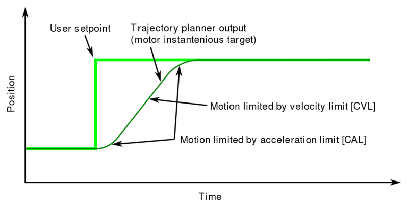
Trajectory planner in GD drives is an internal function to produce smooth acceleration and velocity trajectories based on user input, that may be just a rapid setpoint value change. The main purpose of trajectory planner is to allow creating simple point-to-point motion with minimal complexity from the controller.
Contents
Operation[edit | edit source]
Trajectory planner has two main parameters which define the motion profile limits:
Following example illustrates a case where user setpoint changes instantly, and causes trajectory planner to generate acceleration & velocity limited motion.
Trajectory planner has no limit of how often setpoint may be changed. It is possible to give new setpoint even when motion has not reached it's target position, and output motion still follows the given speed limits.
Application[edit | edit source]
When to use[edit | edit source]
Trajectory planner is mostly used in following cases:
- Point-to-point positon control (controller gives just target position and let drive to perform the motion)
- Simple velocity control tasks (such as spindle)
- Velocity limiting for safety reasons on all position & velocity control mode applications
When to avoid[edit | edit source]
As trajectory planner causes limited rate of change, it is not desirable in applications that demand high bandwidth position or velocity control such as:
- Dual-loop feedback position control, or any system where setpoint of drive is output of another closed loop system
- Systems where external motion controller takes care of acceleration limit calculation and trajectory generation
To prevent trajectory planner from distorting or causing lag in such systems, it can be effectively disabled by setting Acceleration limitCAL to maximum value. Velocity limit may be still used for safety reasons as it will not alter the signal unless setpoint velocity exceeds the Velocity limitCVL limit.
Extending CAL and CVL parameter range[edit | edit source]
Especially when using high resolution feedback devices, one may hit the maximum settable range of CAL and CVL parameters.
Due to the structure of signal path of drive, effective scale of these parameters depend on parameter Setpoint dividerDIV. In other words, adjusting DIV will give different sensitivity to velocity and acceleration limits.
To extend range, use smaller DIV value. It's worth noting that if one adjusts only DIV, then setpoint scaling changes unless also Setpoint multiplierMUL is adusted proportionally.
| Example: default MUL & DIV values are 50 and 50. In order to increase acceleration and velocity range by 10 times, set MUL & DIV to 5 & 5. |
See also[edit | edit source]
In no event the Product Information or parts hereof shall be regarded as guarantee of conditions or characteristics. The Product Information or any part thereof may also not be regarded as a warranty of any kind. No liability of any kind shall be assumed by Author with respect to Product Information or any use made by you thereof, nor shall Author indemnify you against or be liable for any third party claims with respect to such information or any use thereof.
As content of this Wiki may be edited by user community, Granite Devices Oy or it's affiliates do not take any responsibility of the contents of this Wiki. Use information at your own risk. However, Granite Devices staff attempts to review all changes made to this Wiki and keep information trustworthy.
Without written consent, Granite Devices' Products or Intellectual Property shall not be used in situations or installations where living beings, material property, or immaterial property could be harmed by the operation, features or failures of Product. Products may only be used in a way where hazards like moving parts, electric shock, laser radiation, or fire can't be realized even if the content of this Wiki would suggest otherwise.
