Difference between revisions of "Tuning torque controller"
| [checked revision] | [checked revision] |
(adjust text after param template) |
(add TSP1 saturation guide) |
||
| Line 27: | Line 27: | ||
**Make other necessary adjustments to have drive powered and enabled | **Make other necessary adjustments to have drive powered and enabled | ||
*Set-up the test stimulus and capture settings from Testing tab: | *Set-up the test stimulus and capture settings from Testing tab: | ||
| − | **Set target setpoint 1 [[TSP1]] to | + | **Set target setpoint 1 [[TSP1]] to 2000-15000 (see the chapter below for finding the optimum test setpoint) |
**Set delay 1 [[TSD1]] to 0.05 seconds | **Set delay 1 [[TSD1]] to 0.05 seconds | ||
**Set target setpoint 2 [[TSP2]] to 0 | **Set target setpoint 2 [[TSP2]] to 0 | ||
| Line 39: | Line 39: | ||
Once the steps above are done, motor should be generating short torque pulses to a fixed shaft and torque response graphs should appear on the right side of Granity about once in 3-5 seconds. | Once the steps above are done, motor should be generating short torque pulses to a fixed shaft and torque response graphs should appear on the right side of Granity about once in 3-5 seconds. | ||
| + | ===Finding optimium test current (TSP1)=== | ||
| + | To find optimum value for TSP1, enable capture channel called "Motor output voltage" to see how much voltage is driven to motor during rising the edge of torque. For optimum TSP1 value the voltage peak should lie within 20% to 80%. If voltage gets saturated (100%), reduce TSP1 value until it stays below 80%. Images below illustrate the wrong case (first image) and correctly set case (second image). | ||
| + | <gallery widths=400 heights=400> | ||
| + | File:torqueTuningSaturated.png|TSP1 value too high causing output voltage saturation to 100% (A). This will cause torque tuning to look better than it actually is (B). | ||
| + | File:torqueTuningNotSaturated.png|TSP1 value set optimally and peak voltage stays at 60% (C). Now the test reveals that present settings are causing some torque overshooting (D) and we can eliminate it by adjusting ML and MR values. | ||
| + | </gallery> | ||
===Adjusting MR and ML to for optimum torque control=== | ===Adjusting MR and ML to for optimum torque control=== | ||
| Line 75: | Line 81: | ||
*Undo all temporary changes made to settings (such as {{param|TBW}}, {{param|CM}}, {{param|DIV}}, {{param|MUL}}) but leave the optimized {{param|MR}} and {{param|ML}} values active | *Undo all temporary changes made to settings (such as {{param|TBW}}, {{param|CM}}, {{param|DIV}}, {{param|MUL}}) but leave the optimized {{param|MR}} and {{param|ML}} values active | ||
*Save settings to drive memory by clicking ''Save settings on drive non-volatile memory'' button | *Save settings to drive memory by clicking ''Save settings on drive non-volatile memory'' button | ||
| + | |||
==Using drive in torque mode== | ==Using drive in torque mode== | ||
If torque mode is the final desired operating mode, set-up the [[setpoint]] signal source from Granity Goals tab. Also see [[Signal path of motor drive]] for explanation of torque setpoint scale. | If torque mode is the final desired operating mode, set-up the [[setpoint]] signal source from Granity Goals tab. Also see [[Signal path of motor drive]] for explanation of torque setpoint scale. | ||
Revision as of 17:30, 21 October 2015
Torque controller tuning means finding the correct gain values for a torque controller inside the servo drive to achieve a proper response from a torque setpoint change.
Contents
Direct inductance & resistance setting method
In Granity, there is no dedicated torque control PI gains as the software supports entering motor coil inductance and resistance where the suitable PI gains are calculated from.
Method 1 (preferred)
If you are using a drive model that supports automatic measurement of inductance and resistance, follow the instructions here.
Method 2
If the above measurement function is not available, and your motor comes with coil specifications containing phase-to-phase inductance and resistance values, then the only necessary step is to enter the given values into motor Coil resistanceMR and Coil inductanceML parameter fields. In case of troubles with this method, proceed with manual tuning method.
Manual tuning method
Manual tuning of torque controller is some times done in order to optimize the torque controller response or to find the correct motor Coil resistanceMR and Coil inductanceML parameters if unknown. Manual tuning also usually yields better torque response than the direct method which may help tuning of velocity or position tuning.
| If satisfactory performance was achieved by direct inductance & resistance setting method, you may skip the manual tuning method. |
In order to change torque tuning, one needs to change motor Coil resistanceMR and Coil inductanceML parameters until the torque response looks satisfactory.
Preparations

Steps to do to begin torque tuning:
- Ensure that motor is parameterized correctly and working
- Fix the motor shaft so that it cannot rotate under full peak torque of the motor
- Make following parameter changes to Granity and click apply afterwards:
- Set drive in torque control mode Control modeCM
- Set Torque bandwidth limitTBW to maximum
- Choose Serial only setpoint input Control modeCM
- Untick Setpoint smoothingCIS
- Set Goals tab Setpoint dividerDIV and Setpoint multiplierMUL to 50
- Make other necessary adjustments to have drive powered and enabled
- Set-up the test stimulus and capture settings from Testing tab:
- Set target setpoint 1 TSP1 to 2000-15000 (see the chapter below for finding the optimum test setpoint)
- Set delay 1 TSD1 to 0.05 seconds
- Set target setpoint 2 TSP2 to 0
- Set delay1 TSD2 to 0.5 s
- Choose sample rate Sample rateTSR of 10000 Hz or more
- Choose Capture setpoint change ind positive direction from the dropdown
- Tick Continuously repeating capture
- Tick Torque setpoint and Torque achieved from signals
- Tick Start capture to begin continous capture.
- Tick Enable test stimulusTSE to begin a pulsed torque generation
Once the steps above are done, motor should be generating short torque pulses to a fixed shaft and torque response graphs should appear on the right side of Granity about once in 3-5 seconds.
Finding optimium test current (TSP1)
To find optimum value for TSP1, enable capture channel called "Motor output voltage" to see how much voltage is driven to motor during rising the edge of torque. For optimum TSP1 value the voltage peak should lie within 20% to 80%. If voltage gets saturated (100%), reduce TSP1 value until it stays below 80%. Images below illustrate the wrong case (first image) and correctly set case (second image).
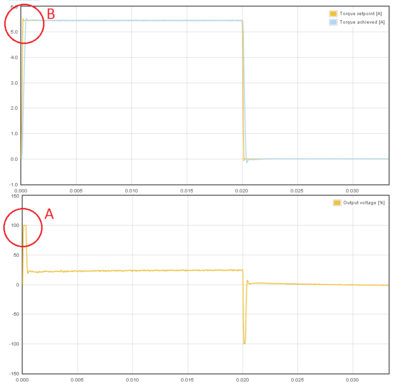
TSP1 value too high causing output voltage saturation to 100% (A). This will cause torque tuning to look better than it actually is (B).
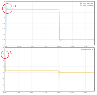
TSP1 value set optimally and peak voltage stays at 60% (C). Now the test reveals that present settings are causing some torque overshooting (D) and we can eliminate it by adjusting ML and MR values.


Adjusting MR and ML to for optimum torque control
The task here is to adjust the Coil resistanceMR and Coil inductanceML parameters to achieve near optimum step response for the torque controller. Observe the images below for guidance.
| If the drive faults during this testing due to overcurrent, try reducing TSP1 value or increase Over current toleranceFOC parameter. Or try radically different Coil resistanceMR and Coil inductanceML values. |

In this case the Coil resistanceMR value has been set too low causing slowly rising achieved torque curve. Such slow response would reduce servo responsiveness.

In the opposite case (too high Coil resistanceMR value) the response shows wavy oscillations and ovesrhoot.

Same kind of phenomenon will be seen if motor Coil inductanceML value is too low. Finding oscillation free tuning is finding the correct balance between the MR and ML as both affect each other.

Too high Coil inductanceML will cause sharp overshooting and high frequency oscillations. Motor may produce audible noise if oscillations are continuous (occurs with way too high ML).

The above image shows near optimum torque response with fast rising edge combined to minimal overshoot.

The above image shows what may happen if motor shaft is not fixed properly (allowed to rotate). This is with the same optimum settings like the previous image.
Steps to do after manual tuning finished
- Stop test stimulus by unticking Enable test stimulusTSE
- Stop scope catpure by unticking Continuously repeating capture
- Undo all temporary changes made to settings (such as Torque bandwidth limitTBW, Control modeCM, Setpoint dividerDIV, Setpoint multiplierMUL) but leave the optimized Coil resistanceMR and Coil inductanceML values active
- Save settings to drive memory by clicking Save settings on drive non-volatile memory button
Using drive in torque mode
If torque mode is the final desired operating mode, set-up the setpoint signal source from Granity Goals tab. Also see Signal path of motor drive for explanation of torque setpoint scale.
Read next
|