Difference between revisions of "SimpleMotion V2 termination with bare cable"
| [checked revision] | [checked revision] |
(Created page with "File:multidrop_estop.png|thumb|500px|Typical SM V2 multidrop bus with E-stop functionality. In this page we instruct to eliminate SMV2BRK and connect stop-switch with bare w...") |
|||
| Line 4: | Line 4: | ||
While the preferred way to terminate [[SimpleMotion V2]] bus is to use [[SMV2BRK]] break-out-board, there is also an option to do it with bare RJ45 Ethernet cable. This page instructs how to achieve proper termination. | While the preferred way to terminate [[SimpleMotion V2]] bus is to use [[SMV2BRK]] break-out-board, there is also an option to do it with bare RJ45 Ethernet cable. This page instructs how to achieve proper termination. | ||
| − | + | Before proceeding, make sure you understand [[SimpleMotion V2 port]]. | |
| − | + | ||
| − | + | ||
==Use as E-stop & Enable input== | ==Use as E-stop & Enable input== | ||
Revision as of 23:26, 30 October 2014
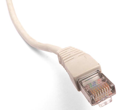
SimpleMotion V2 communication link and Argon drives use RJ45 connectors and cables as physical connection standard. While the preferred way to terminate SimpleMotion V2 bus is to use SMV2BRK break-out-board, there is also an option to do it with bare RJ45 Ethernet cable. This page instructs how to achieve proper termination.
Before proceeding, make sure you understand SimpleMotion V2 port.
Use as E-stop & Enable input
In Argon drive, the same connector acts also as emergencecy stop or Safe torque off input. User may connect a e-stop button directly at the end of device chain to gain reliable stopping mechanism for all linked devices.
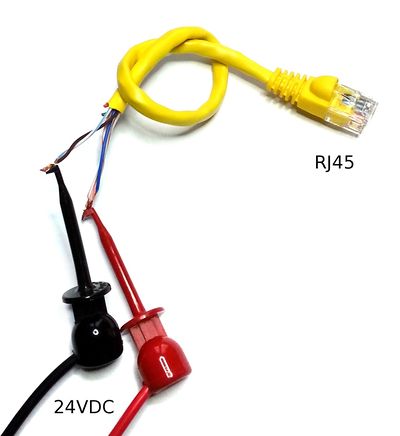
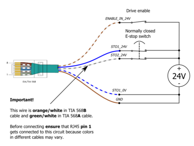
Wiring with bare RJ45 cable

| SimpleMotion V2 devices use pins 3, 6 and 8 (RS485_A,RS485_B and GND) for serial communication. If something interferes these lines, communication may fail or devices may be damaged. Before powering 24V to any of the pins, ensure that pins 3 and 6 are not connected to any external circuit. It's also highly recommended to use current limited 24V power source for initial tests to reduce risk of damage (0.15-0.3A limit). |
Connector pinout
| Pin # | Signal name | Description | Electrical wiring |
|---|---|---|---|
| 1 | STO2_24V | STO input 2 | Supply 24VDC in this pin referenced to GND to disable STO2. 1 |
| 2 | Reserved | Reserved for future use | Do not connect |
| 3 | RS485_A | RS485 signal A | RJ45 cable routes this between devices and SimpleMotion V2 USB adapter |
| 4 | STO1_24V | STO input 1 24V in | Supply 24VDC between STO1_24V and STO1_0V to disable STO1. STO1 inputs are floating and isolated from GND. 1, 2 |
| 5 | STO1_0V | STO input 1 0V in | |
| 6 | RS485_B | RS485 signal B | RJ45 cable routes this between devices and SimpleMotion V2 USB adapter |
| 7 | ENABLE_IN_24V | Drive enable control signal | Supply 24VDC in this pin referenced to GND to set drive in enabled state. |
| 8 | GND | Ground reference for: RS485, STO2 and ENABLE_IN | RJ45 cable routes this between devices and SimpleMotion V2 USB adapter. For enable & STO connect this to external 24V power supply ground. |
1) STO1 and STO2 are controlling two independent Safe torque off methods. Both must be supplied 24V simultaneously to enable torque to the motor.
2) STO1 has limited functionality on Argon if HV DC bus is shared between drives or external DC voltage is supplied. For more info, see Argon user guide/J4 connector wiring.
| Even when RJ45 connector and cables are being used in Ethernet and SimpleMotion, these protocols are not electrically compatible. Never connect SimpleMotion device to Ethernet device. |


