Difference between revisions of "IONI connector pinout"
| [checked revision] | [checked revision] |
(→Feedback device signals) |
|||
| Line 211: | Line 211: | ||
| A/B/C-||RS422 receiver, 2.7-5.5V signal level|| - ||1.1k pull to 2.5V | | A/B/C-||RS422 receiver, 2.7-5.5V signal level|| - ||1.1k pull to 2.5V | ||
|} | |} | ||
| + | ==Electrical interface modes (software selectable)== | ||
| + | IONI supports various function mappings to I/O signals and is selectable through [[Granity]] [[CEI|CEI Electrical interface parameter]]. The differences between modes are: | ||
| + | |||
| + | {| class="wikitable" | ||
| + | |- | ||
| + | ! Mode !! Description !! Effects | ||
| + | |- | ||
| + | | Standard || The default mode || I/O assignments as described in pinout | ||
| + | |- | ||
| + | | IONICUBE || Mode for [[IONICUBE]] that is compatible with [[Mach3]] software || | ||
| + | * In addition to rising edge of GPI4, also rising edge on Enable will clear fault state. In standard mode Enable input will not clear faults. | ||
| + | * GPO3 (fault state) output will go logic low after Enable signal goes low. In standard mode GPO3 stays high until faults are cleared. | ||
| + | |- | ||
| + | | IONIZER || Not yet implemented, do not use || - | ||
| + | |} | ||
| + | |||
[[category:IONI]] | [[category:IONI]] | ||
[[category:IONI user guide]] | [[category:IONI user guide]] | ||
Revision as of 12:45, 31 March 2015
IONI card edge connector fits into a standard PCI-Express 8X socket connector.
Contents
Pinout


| Color |
|---|
| Power pin |
| Input pin |
| Output pin |
| Mixed or other purpose |
The pinout of IONI drive is provided in the following table.
- I/O and low voltage signals
| Pin | Signal name | Pin | Signal name | |
|---|---|---|---|---|
| A1 | GND | B1 | 5V_IN | |
| A2 | RS485_A | B2 | RS485_B | |
| A3 | ADDRSEL1 | B3 | ADDRSEL2 | |
| A4 | HSIN1 | B4 | HSIN2 | |
| A5 | ANAIN- | B5 | ANAIN+ | |
| A6 | GPI1 | B6 | GPI2 | |
| A7 | GPI3 | B7 | GPI4 | |
| A8 | GPO1 | B8 | GPO2 | |
| A9 | GPO3 | B9 | GPO4 | |
| A10 | GPO5 | B10 | GPI5 | |
| A11 | REGEN_OUT | B11 | MECH_BRAKE_OUT | |
| A12 | ENABLE_IN | B12 | Reserved/NC | |
| A13 | STO2 | B13 | HALL_W | |
| A14 | HALL_V | B14 | HALL_U | |
| A15 | A- | B15 | A+ | |
| A16 | B- | B16 | B+ | |
| A17 | C- | B17 | C+ |
- Power signals
| Pin | Signal name | Pin | Signal name | |
|---|---|---|---|---|
| A18-A22 | GND | B18 | Not connected | |
| A23 | Not connected | B19-B22 | HV+ | |
| A24-A27 | PHASE1 | B23 | Not connected | |
| A28 | Not connected | B24-B27 | PHASE2 | |
| A29-A37 | PHASE3 | B28 | Not connected | |
| A38 | Not connected | B29-B37 | PHASE4 | |
| A39-A43 | PHASE1 | B38 | Not connected | |
| A44 | Not connected | B39-B43 | PHASE2 | |
| A45-A49 | GND | B44 | Not connected | |
| B45-B49 | HV+ |
Note 1: pins marked as Not connected are left empty for to make larger clearance for high voltage signals. Leave these pins unconnected on motherboard designs.
Note 2: Each power signal is present in two pin groups (internally parallel) and these signals should be wired parallel on motherboard.
Signal assignment
General purpose I/O (GPI/GPO)
The table below summarizes the default functions for GPIO pins.
| Connecting GPI/GPO's are not mandatory. All of the same functions may be also accessed via SimpleMotion V2 interface. |
| Signal name | Function | Used for | Remarks |
|---|---|---|---|
| GPI1 | Home switch | Homing reference switch (optional), can also disable homing, or use Hard-stop homing without switch | Note 1 |
| GPI2 | Enable positive feed | Axis positive direction end limit switch (optional) | Normally closed switch. When switch is open, motion/force in positive direction is prevented. 1 |
| GPI3 | Enable negative feed | Axis negative direction end limit switch (optional) | Normally closed switch. When switch is open, motion/force in negative direction is prevented. 1 |
| GPI4 | Clear faults | Rising logic edge on this pin will clear fault state of drive | In IONICUBE mode, also rising edge of enable signal will clear faults. |
| GPI5 | Start homing | Rising logic edge on this pin will start homing if homing is enabled | |
| GPO1 | Servo ready | Use to indicate controller that drive is ready | Logic 1 when drive has been initialized, enabled and ready to follow setpoint commands. If homing is enabled, then servo ready will be logic 1 after homing is successfully completed. |
| GPO2 | Tracking error warning | Use to indicate controller when drive is having difficulties following the setpoint before a tracking fault occurs | Logic 1 when tracking error (position or velocity, depending on control mode) is greater than 1/8 of configured fault trigger level. |
| GPO3 | Fault state | Use to indicate controller that drive is stopped due to fault state | In IONICUBE mode GPO3 goes logic 0 after when enable signal is set low (for Mach3 compatibility). |
| GPO4 | 2-way travel allowed | Use to indicate controller when axis is allowed to move in both directions (i.e. any limit switches not hit or axis lies within an optional homing defined limited travel range) | |
| GPO5 | Reserved |
1) Connect switch between GND and GPIn pin
Setpoint signals
Setpoint mode is selected by software with parameter CRI and behavior is affected by parameters CIS, MUL, DIV, CAO and CED.
| Drive listens setpoint commands also always through SimpleMotion V2 interface regardess of CRI paramter setting. |
| Signal name | Function | Used for | Remarks |
|---|---|---|---|
| HSIN1 | High speed digital input 1 | Depending in setpoint mode, can be either: direction input (of pulse/dir or PWM) or quadrature A input | |
| HSIN2 | High speed digital input 2 | Depending in setpoint mode, can be either: pulse input (of pulse/dir), PWM input or quadrature B input | |
| ANAIN- | Differential analog negative input | Used for analog setpoint mode | Setpoint voltage is the voltage difference between ANAIN+ and ANAIN- |
| ANAIN+ | Differential analog positive input | Used for analog setpoint mode |
Feedback device signals
| Signal name # | Electrical type (in most feedback device modes) | Alternate electrical type (in some feedback device modes) | Connection with various feedback devices |
|---|---|---|---|
| HALL_W | Digital input W | Hall sensor input, phase W | |
| HALL_V | Digital input V | Hall sensor input, phase V | |
| HALL_U | Digital input U | Hall sensor input, phase U | |
| A- | Differential input A- | Analog input A- | Quadrature encoder (A channel)/SinCos A |
| A+ | Differential input A+ | Analog input A+ | |
| B- | Differential input B- | Analog input B+ | Quadrature encoder (B channel)/SinCos B |
| B+ | Differential input B+ | Analog input B- | |
| C- | Differential input C- | Quadrature encoder index channel (Z channel) | |
| C+ | Differential input C+ | ||
| In case of single-ended encoder, connect encoder's A, B, Z only to drive's A+, B+ and C+ and leave drive's A-, B- and C- unconnected. |
| With differential Hall sensor (which provides U+, U-, V+, V-, W+ and W-, connect only sensor's U+, V+ and W+ to drive's HALL_U/V/W. |
| Never connect sensor negative outputs (A-/B-/C-/U-/V-/W-) to GND. Connect them to drive's A-/B-/C- or leave unconnected. |
| Feedback devices with differential signaling may use varying naming schemes of signal pairs. For example differential signal X (which contains two electrical wires) may be denoted as: X+ and X-, or X and \X or X and X. In this Wiki we mark them X+ and X-. Some Fanuc encoders have quadrature signals named as PCA, /PCA, PCB, /PCB, PCZ and /PCZ which are equivalent to A, B and Z signal pairs. |
Other signals
| Signal name | Function | Used for | Remarks |
|---|---|---|---|
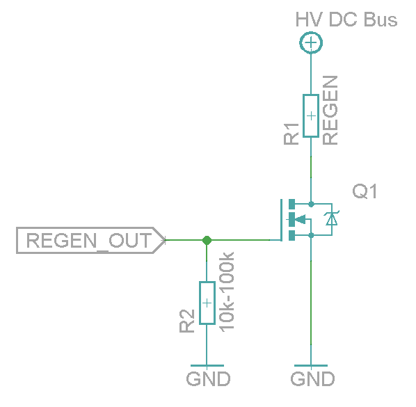
| REGEN_OUT | Regenerative resistor control output | Use to control optional regenerative resistor to prevent excessive voltage generation in HV DC bus during motor deceleration. | A buffer circuit is needed for resistor, such as a logic level MOSFET. See example schematic here. |
| MECH_BRAKE_OUT | Mechanical holding brake control output | Use to control optional holding brake of motor | A buffer circuit is needed to drive a solenoid brake, such as a logic level MOSFET. See example schematic here. |
| ENABLE_IN | Drive enable input signal (always required) | Use to enable drive and allow motor to initialize and operate | Accepts up to 24V voltage level, but works also with 3V level signal |
| STO2 | Safe torque off input signal (always required) | Use to allow motor to produce torque (activate power stage) | Accepts up to 24V voltage level, but works also with 5V level signal. STO is inactive (allows torque) when logic high is supplied. |
Electrical ratings
| Signal names | Allowed input voltages/output voltage | Internal input/output impedance (Ω) | Internal pull impedance (Ω) |
|---|---|---|---|
| 5V_IN | 5V +/-10% | - | - |
| HV+ | 0 – 55 V | - | - |
| RS485_A/B | RS485 serial bus, 2.7-5.5V signal level | >10k | - |
| ADDRSEL1, ADDRSEL2 | External address setting pull-down resistors to ground (minimum 2.2 kΩ). See article Setting IONI bus address. | - | 2.2k pull-up |
| HSIN1, HSIN2 | Logic low -0.3-1.0V, logic high 2.7-5.5V | - | 2.2k pull-up |
| ANAIN-, ANAIN+ | +/- 11V | 8k | - |
| GPI1...GPI4 | Logic low -0.3-1.0V, logic high 2.7-5.5V | - | 2.2k pull-up |
| GPI5 | Logic low -0.3-1.0V, logic high 2.7-5.5V | - | ~20-50k pull-up |
| GPO1...GPO5 | Logic low 0V, logic high 3.3V | 220 | - |
| MECH_BRAKE_OUT | Logic low 0V, logic high 3.3V | 220 | - |
| REGEN_OUT | Logic low 0V, logic high 3.3V | 220 | - |
| ENABLE_IN | Logic low -0.3-1.0V, logic high 2.7-26V | 5k | 10k pull-down |
| STO2 | Logic low -0.3-2.0V, logic high 4.5-26V | 8k | 20k pull-down |
| HALL_U/V/W | Logic low -0.3-1.0V, logic high 2.7-5.5V | - | 2.2k |
| A/B/C+ | RS422 receiver, 2.7-5.5V signal level | - | 2.2k |
| A/B/C- | RS422 receiver, 2.7-5.5V signal level | - | 1.1k pull to 2.5V |
Electrical interface modes (software selectable)
IONI supports various function mappings to I/O signals and is selectable through Granity CEI Electrical interface parameter. The differences between modes are:
| Mode | Description | Effects |
|---|---|---|
| Standard | The default mode | I/O assignments as described in pinout |
| IONICUBE | Mode for IONICUBE that is compatible with Mach3 software |
|
| IONIZER | Not yet implemented, do not use | - |