Difference between revisions of "SimuCUBE install guide old"
| [checked revision] | [checked revision] |
(Tag: VisualEditor) |
(→Overview) |
||
| Line 17: | Line 17: | ||
** 1 or 2 Mini-USB cables | ** 1 or 2 Mini-USB cables | ||
** IEC C13 power cord (similar to most PC peripherals use) | ** IEC C13 power cord (similar to most PC peripherals use) | ||
| − | ** | + | ** Motor cables: power cable (with bare wire ends) and motor [[feedback devices|feedback device]] (encoder) cable. If the feedback device cable does not come with SimuCUBE (or [[IONI]] [[ARGON|or ARGON]]) compatible feedback device connector installed, then having a ''two row male D-Sub 15 connector'', ''connector hood'', and ''soldering tools'' are also necessary to make the cable. |
| − | + | ||
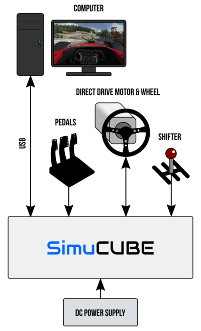
{{Picturebox|simucube chart.png|400px|caption=SimuCUBE complete system overview. Pedals and shifter are optional and power supply is usually integrated inside the SimuCUBE controller box.}} | {{Picturebox|simucube chart.png|400px|caption=SimuCUBE complete system overview. Pedals and shifter are optional and power supply is usually integrated inside the SimuCUBE controller box.}} | ||
Revision as of 19:59, 27 June 2016
This is the guide to install and configure SimuCUBE based Force feedback system (FFB) from the factory state to a working state. This is for you if you have assembled SimuCUBE based system ready for use, or a system needing just motor wiring to the system.
If you have bare SimuCUBE mother board or SimuCUBE kit that needs assembly, see SimuCUBE documentation portal for earlier sections of the documentation.
| This page is under construction. Don't use this page until this notice is removed. |
SimuCUBE based Force feedback system (FFB) pose high mechanical danger that may cause serious injuries to living beings, cause damage to external property or loss of profits. Always operate SimuCUBE based system with maximal caution.
|
Overview
The usage of SimuCUBE system involves connecting all necessary parts together and configuring software and parameters to work with the actual force feedback applications. This guide assumes that user already has necessary parts, including:
- A SimuCUBE control box (with integrated power supply)
- A servo motor to be used as force feedback actuator
- A steering wheel attached to a motor
- A PC computer with at least one USB 2.0 port and Microsoft Windows 7 or later Windows version
- Third party firmware file to be installed in SimuCUBE (specifically "MMos" firmware from the racing simulator community)
- Wiring materials:
- 1 or 2 Mini-USB cables
- IEC C13 power cord (similar to most PC peripherals use)
- Motor cables: power cable (with bare wire ends) and motor feedback device (encoder) cable. If the feedback device cable does not come with SimuCUBE (or IONI or ARGON) compatible feedback device connector installed, then having a two row male D-Sub 15 connector, connector hood, and soldering tools are also necessary to make the cable.

SimuCUBE complete system overview. Pedals and shifter are optional and power supply is usually integrated inside the SimuCUBE controller box.
Installation step-by-step
Installation procedure main steps are:
- PART 1: Install the Force feedback firmware in the SimuCUBE. This is necessary as SimuCUBE ships without firmware for the time being.
- PART 2: Connect motor to SimuCUBE. If motor does not come with SimuCUBE (or IONI or ARGON) compatible feedback device connector, then assembling a connector is also necessary.
- PART 3: Configuring the IONI drive to match the motor properties
- PART 4: Configure force feedback settings
- PART 5: Optional: wire pedals, buttons and other input devices to SimuCUBE
For common pitfalls and problems, see SimuCUBE troubleshooting.
