Difference between revisions of "IONI & IONICUBE user guide/LED indicators"
From Granite Devices Knowledge Wiki
| [checked revision] | [checked revision] |
m (Text replacement - "\[\[([A-Z]{2,3})\]\]" to "{{param|$1}}") |
|||
| Line 59: | Line 59: | ||
|- | |- | ||
| Run || [[File:4ON.gif]] || On ||yes | | Run || [[File:4ON.gif]] || On ||yes | ||
| + | |- | ||
| + | | Other/uncategorized (not any of above). For details, connect with Granity and see status bits. || [[File:4LLSS.gif]] || LLSS || Yes or No | ||
|} | |} | ||
{{next|[[IONI & IONICUBE user guide/Drive parameterization]]}} | {{next|[[IONI & IONICUBE user guide/Drive parameterization]]}} | ||
| − | + | ||
| − | + | ||
[[Category:IONI]] | [[Category:IONI]] | ||
| + | [[Category:IONI_troubleshooting]] | ||
| + | [[Category:IONI_user_guide]] | ||
Revision as of 16:22, 1 September 2015
IONI has two on-board led indicators which have dedicated indicating tasks:- LED1 Motor control state indicator (green)
- LED2 Fault indicator (orange)
How to read indications
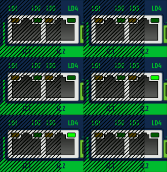
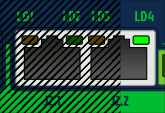
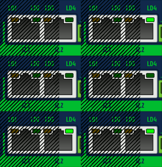
- LED1 and LED2 have programmed blinking sequences. Sequences consists series of short (S) and long (L) light pulses. For example LLS means the led will blink two long flashs and then one short flash. After sequence there will be a pause before the sequence repeats.
- LED1 and LED2 are independent and can show fault and motor state simultaneously. To easier reading sequence, cover one led with a thumb to be able to concentrate to one led.
- LED2 and shows the first fault occurred if multiple fault states are active simultaneously.
- LED1 and LED2 are flashing together if device is in a firmware upgrade mode (DFU).
List of all LED1 and LED2 sequences
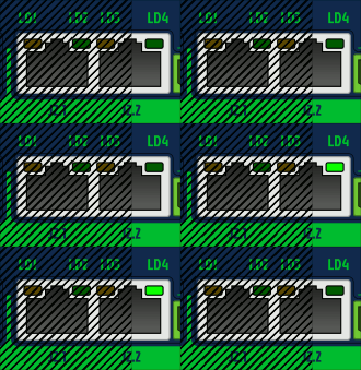
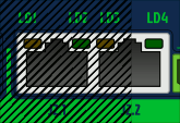
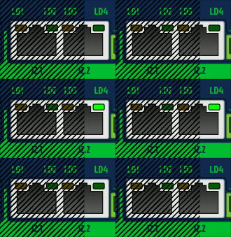
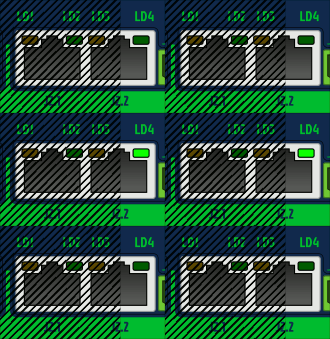
To see animated images, view this Wiki page in a web browser with animations enabled. The animations show Argon front panel, but the blinking sequences of IONI are equivalent when LED1=LD4 and LED2=LD3.
Faults
Only LED2 is being controlled by these faults, except in DFU mode when both leds blink together.
| Fault reason | LED sequence | LED sequence as text |
|---|---|---|
| Hardware | 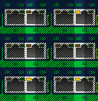 |
LLSS |
| Progral or memory | 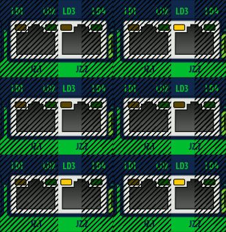 |
LSLL |
| Internal comm error (CRC) | 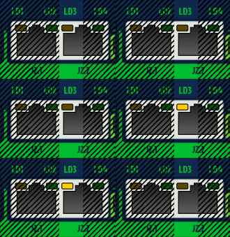 |
LSL |
| Initialization | 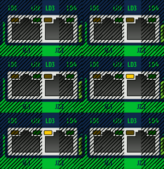 |
LSS |
| Over current | 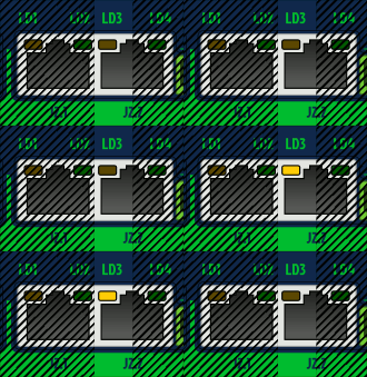 |
SLL |
| Over temperature | 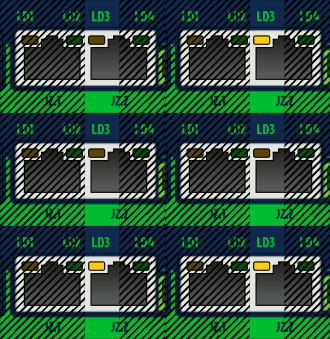 |
LSLS |
| Over voltage | 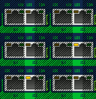 |
SLS |
| Following error | 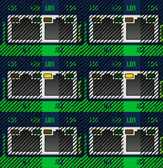 |
LS |
| Under voltage | 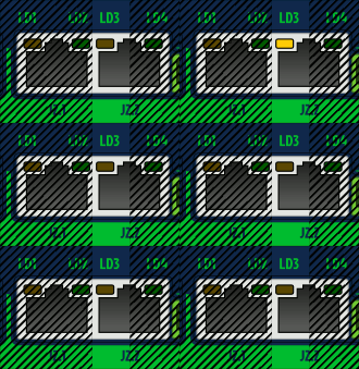 |
SL |
| Motion blocked or motor runaway |  |
SSL |
| Setpoint range exceeded | 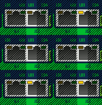 |
LSSL |
| Other/unknown, possibly configuration error such as motor mode Motor typeMT not selected | 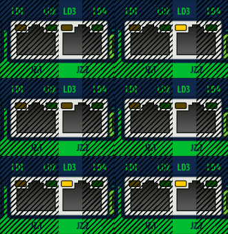 |
SSSL |
Motor control states
Only LED1 is being controlled by these states.
| Read next |
