Difference between revisions of "Setting device bus address"
| [checked revision] | [checked revision] |
(→Bus termination) |
|||
| Line 80: | Line 80: | ||
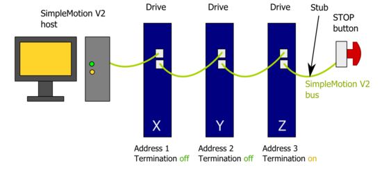
[[File:Multidrop addressing.png|thumb|550px|Proper configuration of devices on a bus]]SimpleMotion V2 bus must be terminated for reliable communication. This means that last device of the bus must have termination DIP switch set to On position. | [[File:Multidrop addressing.png|thumb|550px|Proper configuration of devices on a bus]]SimpleMotion V2 bus must be terminated for reliable communication. This means that last device of the bus must have termination DIP switch set to On position. | ||
| − | Bus may be also ''alternatively'' terminated with external 100 ohm resistor connected between RS485_A and RS485_B wires at the end of bus cable chain (see [[ | + | Bus may be also ''alternatively'' terminated with external 100 ohm resistor connected between RS485_A and RS485_B wires at the end of bus cable chain (see [[SimpleMotion V2 port]]). If DIP switch termination is used, then drive internal 100 ohm resistor is connected across the A and B wires. |
| + | |||
===Bus stub=== | ===Bus stub=== | ||
If an E-stop button is connected with RJ45 cable after the last device, a bus '''stub''' is formed. Stub must not be longer than 30 cm or 1 foot to ensure bus operation. | If an E-stop button is connected with RJ45 cable after the last device, a bus '''stub''' is formed. Stub must not be longer than 30 cm or 1 foot to ensure bus operation. | ||
Revision as of 00:56, 5 January 2013
All SimpleMotion V2 compatible devices have a settable address that identifies the device on a multidrop communication bus. Each device on the sharint the same bus must have an unique address number to make error free communication possible. For example configuring bus address is required to establish a connection with Granity software.
If two or more devices are incorrectly set to have same address, packet collisions will happen in the bus causing communication failures.
Setting bus address various devices
The method of how address is set depends on device hardware implementation. This chapter lists methods for Granite Devices products.
Argon
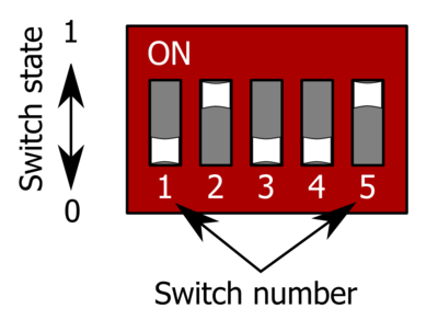
Argon (servo drive) has a 5 channel DIP switch that sets the address. The table below lists all possible settings of DIP switch settings.
| Address | Bus termination | DIP switch setting (switches from 1 to 5) |
|---|---|---|
| 255 (firmware upgrade mode) | Off | 00000 |
| 255 (firmware upgrade mode) | On | 00001 |
| 1 | Off | 00010 |
| 1 | On | 00011 |
| 2 | Off | 00100 |
| 2 | On | 00101 |
| 3 | Off | 00110 |
| 3 | On | 00111 |
| 4 | Off | 01000 |
| 4 | On | 01001 |
| 5 | Off | 01010 |
| 5 | On | 01011 |
| 6 | Off | 01100 |
| 6 | On | 01101 |
| 7 | Off | 01110 |
| 7 | On | 01111 |
| 8 | Off | 10000 |
| 8 | On | 10001 |
| 9 | Off | 10010 |
| 9 | On | 10011 |
| 10 | Off | 10100 |
| 10 | On | 10101 |
| 11 | Off | 10110 |
| 11 | On | 10111 |
| 12 | Off | 11000 |
| 12 | On | 11001 |
| 13 | Off | 11010 |
| 13 | On | 11011 |
| 14 | Off | 11100 |
| 14 | On | 11101 |
| 15 | Off | 11110 |
| 15 | On | 11111 |
Bus termination
SimpleMotion V2 bus must be terminated for reliable communication. This means that last device of the bus must have termination DIP switch set to On position.Bus may be also alternatively terminated with external 100 ohm resistor connected between RS485_A and RS485_B wires at the end of bus cable chain (see SimpleMotion V2 port). If DIP switch termination is used, then drive internal 100 ohm resistor is connected across the A and B wires.
Bus stub
If an E-stop button is connected with RJ45 cable after the last device, a bus stub is formed. Stub must not be longer than 30 cm or 1 foot to ensure bus operation.
Methods to elimiate the stub on E-stop cable:
- Cut the A and B wires from the cable near connector and leave only the E-stob button wires left
- Alternatively, connect termination resistor at end of A and B pair and leave DIP switch termination off.

