Configuring IONI drive in SimuCUBE
Each SimuCUBE system consists one IONI Servo & Stepper Drive that is controls the motor of Force feedback system (FFB). This page helps setting correct parameters to IONI drive.
Contents
Preparations
- Download Granity software
- Connect SimuCUBE X4 to PC with USB cable
- Power on SimuCUBE
- Wait until windows has recognized the device and installed driver
- Start Granity software
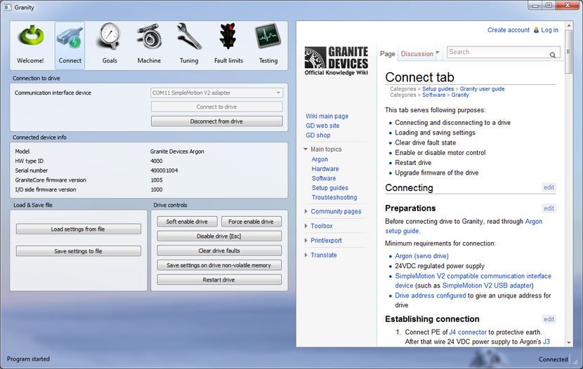
- Connect to IONI by clicking Connect to drive button
-
- Once list of found devices pop-up, select the IONI drive and click Open

If everything went fine, we are now connected to IONI and change it's settings. If not, see SimuCUBE troubleshooting and Device connection troubleshooting.
Upgrading IONI firmware
First it is recommended to upgrade to the latest IONI firmware:
- Download latest IONI firmware from IONI firmware releases
- Follow instructions of Granity user guide/Uploading a firmware
- Connect again into drive by choosing Connect to drive just like we did first time
- Proceed to Loading motor configuration file or Configuring motor manually chapter
Loading motor configuration file
If you have pre-made configuration file made to your motor and SimuCUBE, you may follow this chapter to load it in the IONI and skip the next chapter Configuring motor.
- Click Load settings from file
- Select the file and open it
- Click Save settings to drive non-volatile memory and answer yes to questions of applying settings and restarting drive afterwards
- All done, proceed to Testing settings chapter
Configuring motor manually
All settings except the one mentioned here should be kept at their factory defaults. If unsure which settings are factory defaults, then repeat firmware upgrade procedure and tick the Reset device to factory state checkbox before uploading the firmware.
Following settings are constant and always required with SimuCUBE:
| Granity tab | Parameter | Value | Notes |
|---|---|---|---|
| Goals | Control modeCM | Torque control | |
| Goals | Electrical interfaceCEI | SimuCUBE | |
| Goals | Setpoint inputCRI | Pulse Width Modulation | |
| Goals | Enable direction inputCED | On (ticked) | |
| Fault limits | Over voltage fault thresholdFOV | 49V | Assuming 48 VDC regulated power supply |
| Fault limits | Under voltage fault thresholdFUV | 30V | Assuming 48 VDC regulated power supply |
| Fault limits | Over current toleranceFOC | High | Change this only if over current fault problems occur with the motor |
| Machine | Maximum peak powerMPP | Your power supply rating in watts | Granite Devices SimuCUBE systems are have one of these ratings: 320W, 480W or 720W. Use value from your model. If under voltage faults occur, try reducing this value little bit (like 10-30W). |
Motor parameters depend on the attached motor type and specifications. Refer your motor manufacturer's data sheet to get the correct values in the following fields:
| Granity tab | Parameter | Value | Notes |
|---|---|---|---|
| Machine | Motor typeMT | 3 phase AC or BLDC | |
| Machine | Pole countMPC | 8 | 8 is a typical value, however 4, 6 are common as well |
| Machine | Continuous current limitMCC | Maximum motor continuous current | Most AC motors specify current as RMS value. Value in this field is entered as Peak value of sine. To covert RMS current to peak value of sine, multiply it by 1.41. |
| Machine | Peak current limitMMC | Motor peak current rating | Most AC motors specify current as RMS value. Value in this field is entered as Peak value of sine. To covert RMS current to peak value of sine, multiply it by 1.41.
This defines the maximum torque that system will produce. For safety reasons, it is recommended to set this value to 20% of motor specified value until system operation has been verified. |
| Machine | Coil resistanceMR | Motor phase-to-phase resistance (from motor data sheet) | |
| Machine | Coil inductanceML | Motor phase-to-phase inductance (from motor data sheet) | |
| Machine | Feedback deviceFBD | Motor feedback device type | If unsure, choose Quadrature encoder 1 |
| Machine | Feedback device resolutionFBR | Encoder resolution in pulses per revolution | Typical motors have 2500 PPR or 5000 PPR encoder |
| Machine | Invert feedback directionFBI | Disabled/Enabled | Try first without enabling this, and later with inverting this setting if motor testing section shows problems |
| Tuning | Torque bandwidth limitTBW | 680 Hz | Sets maximum torque bandiwdth of motor. Values between 220 to 680 Hz recommended for FFB systems. |
Testing settings
In no event the Product Information or parts hereof shall be regarded as guarantee of conditions or characteristics. The Product Information or any part thereof may also not be regarded as a warranty of any kind. No liability of any kind shall be assumed by Author with respect to Product Information or any use made by you thereof, nor shall Author indemnify you against or be liable for any third party claims with respect to such information or any use thereof.
As content of this Wiki may be edited by user community, Granite Devices Oy or it's affiliates do not take any responsibility of the contents of this Wiki. Use information at your own risk. However, Granite Devices staff attempts to review all changes made to this Wiki and keep information trustworthy.
Without written consent, Granite Devices' Products or Intellectual Property shall not be used in situations or installations where living beings, material property, or immaterial property could be harmed by the operation, features or failures of Product. Products may only be used in a way where hazards like moving parts, electric shock, laser radiation, or fire can't be realized even if the content of this Wiki would suggest otherwise.