IONI connector pinout
IONI card edge connector fits into a standard PCI-Express 8X socket connector. This page lists electrical and functional specifications of each pin.
Contents
Pinout[edit | edit source]


| Color |
|---|
| Power pin |
| Input pin |
| Output pin |
| Mixed or other purpose |
The pinout of IONI drive is provided in the following table.
- I/O and low voltage signals
| Pin | Signal name | Pin | Signal name | |
|---|---|---|---|---|
| A1 | GND | B1 | 5V_IN | |
| A2 | RS485_A | B2 | RS485_B | |
| A3 | ADDRSEL1 | B3 | ADDRSEL2 | |
| A4 | HSIN1 | B4 | HSIN2 | |
| A5 | ANAIN- | B5 | ANAIN+ | |
| A6 | GPI1 | B6 | GPI2 | |
| A7 | GPI3 | B7 | GPI4 | |
| A8 | GPO1 | B8 | GPO2 | |
| A9 | GPO3 | B9 | GPO4 | |
| A10 | GPO5 | B10 | GPI5 | |
| A11 | REGEN_OUT | B11 | MECH_BRAKE_OUT | |
| A12 | ENABLE_IN | B12 | Reserved/NC | |
| A13 | STO2 | B13 | HALL_W | |
| A14 | HALL_V | B14 | HALL_U | |
| A15 | A- | B15 | A+ | |
| A16 | B- | B16 | B+ | |
| A17 | C- | B17 | C+ |
- Power signals
| Pin | Signal name | Pin | Signal name | |
|---|---|---|---|---|
| A18-A22 | GND | B18 | Not connected | |
| A23 | Not connected | B19-B22 | HV+ | |
| A24-A27 | PHASE1 | B23 | Not connected | |
| A28 | Not connected | B24-B27 | PHASE2 | |
| A29-A37 | PHASE3 | B28 | Not connected | |
| A38 | Not connected | B29-B37 | PHASE4 | |
| A39-A43 | PHASE1 | B38 | Not connected | |
| A44 | Not connected | B39-B43 | PHASE2 | |
| A45-A49 | GND | B44 | Not connected | |
| B45-B49 | HV+ |
- Connection to motor
| Signal name | AC/BLDC motor | Brush DC motor | Stepping motor |
|---|---|---|---|
| GND | Connect motor cable shield and motor frame to power GND | ||
| PHASE1 | U (some motors R) | Armature + | Coil A.1 |
| PHASE2 | V (some motors S) | Armature - | Coil A.2 |
| PHASE3 | W (some motors T) | Connect to PHASE2 | Coil B.1 |
| PHASE4 | Not connected | Connect to PHASE1 | Coil B.2 |
Note 1: pins marked as Not connected are left empty for to make larger clearance for high voltage signals. Leave these pins unconnected on motherboard designs.
Note 2: Each power signal is present in two pin groups (internally parallel) and these signals should be wired parallel on motherboard.
Signal assignment[edit | edit source]
General purpose I/O (GPI/GPO)[edit | edit source]
The table below summarizes the default functions for GPIO pins.
| Connecting GPI/GPO's are not mandatory. All of the same functions may be also accessed via SimpleMotion V2 interface. |
| Signal name | Function | Used for | Remarks |
|---|---|---|---|
| GPI1 | Home switch | Homing reference switch (optional), can also disable homing, or use Hard-stop homing without switch | Note 1 |
| GPI2 | Enable positive feed | Axis positive direction end limit switch (optional) | Normally closed switch. When switch is open, motion/force in positive direction is prevented. 1 |
| GPI3 | Enable negative feed | Axis negative direction end limit switch (optional) | Normally closed switch. When switch is open, motion/force in negative direction is prevented. 1 |
| GPI4 | Clear faults | Rising logic edge on this pin will clear fault state of drive | In IONICUBE mode, also rising edge of enable signal will clear faults. |
| GPI5 | Start homing | Rising logic edge on this pin will start homing if homing is enabled | |
| GPO1 | Servo ready | Use to indicate controller that drive is ready | Logic 1 when drive has been initialized, enabled and ready to follow setpoint commands. If homing is enabled, then servo ready will be logic 1 after homing is successfully completed. |
| GPO2 | Tracking error warning | Use to indicate controller when drive is having difficulties following the setpoint before a tracking fault occurs | Logic 1 when tracking error (position or velocity, depending on control mode) is greater than 1/8 of configured fault trigger level. |
| GPO3 | Fault state (active low) | Use to indicate controller that drive is stopped due to fault state | In IONICUBE mode GPO3 goes logic 0 after when enable signal is set low (for Mach3 compatibility). GPO3 is open drain type to allow wired and connection. |
| GPO4 | 2-way travel allowed | Use to indicate controller when axis is allowed to move in both directions (i.e. any limit switches not hit or axis lies within an optional homing defined limited travel range) |
|
| GPO5 | Reserved | Feel free to request custom signal from Granite Devices support to be added in this output. For example fan control or custom status output. Changes can be made in customer specific firmware. |
1) Connect switch between GND and GPIn pin
See also Drive status & fault bits explained.
Setpoint signals[edit | edit source]
Setpoint mode is selected by software with parameter Setpoint inputCRI and behavior is affected by parameters Setpoint smoothingCIS, Setpoint multiplierMUL, Setpoint dividerDIV, Setpoint offset nullingCAO and Enable direction inputCED.
| Drive listens setpoint commands also always through SimpleMotion V2 interface regardess of Setpoint inputCRI paramter setting. |
| Signal name | Function | Used for | Remarks |
|---|---|---|---|
| HSIN1 | High speed digital input 1 | Depending on setpoint mode, can be either:
| |
| HSIN2 | High speed digital input 2 | Depending on setpoint mode, can be either:
| |
| ANAIN- | Differential analog negative input | Used for analog setpoint mode | Setpoint voltage is the voltage difference between ANAIN+ and ANAIN- |
| ANAIN+ | Differential analog positive input | Used for analog setpoint mode |
Feedback device signals[edit | edit source]
| Signal name # | Electrical type (in most feedback device modes) | Alternate electrical type (in some feedback device modes) | Connection with various feedback devices |
|---|---|---|---|
| HALL_W | Digital input W | Hall sensor input, phase W | |
| HALL_V | Digital input V | Hall sensor input, phase V | |
| HALL_U | Digital input U | Hall sensor input, phase U | |
| A- | Differential input A- | Analog input A- | Quadrature encoder (A channel)/SinCos A |
| A+ | Differential input A+ | Analog input A+ | |
| B- | Differential input B- | Analog input B+ | Quadrature encoder (B channel)/SinCos B |
| B+ | Differential input B+ | Analog input B- | |
| C- | Differential input C- | Quadrature encoder index channel (Z channel) | |
| C+ | Differential input C+ | ||
| In case of single-ended encoder, connect encoder's A, B, Z only to drive's A+, B+ and C+ and leave drive's A-, B- and C- unconnected. |
| With differential Hall sensor (which provides U+, U-, V+, V-, W+ and W-, connect only sensor's U+, V+ and W+ to drive's HALL_U/V/W. |
| Never connect sensor negative outputs (A-/B-/C-/U-/V-/W-) to GND. Connect them to drive's A-/B-/C- or leave unconnected. |
| Feedback devices with differential signaling may use varying naming schemes of signal pairs. For example differential signal X (which contains two electrical wires) may be denoted as: X+ and X-, or X and \X or X and X. In this Wiki we mark them X+ and X-. Some Fanuc encoders have quadrature signals named as PCA, /PCA, PCB, /PCB, PCZ and /PCZ which are equivalent to A, B and Z signal pairs. |
Other signals[edit | edit source]
| Signal name | Function | Used for | Remarks |
|---|---|---|---|
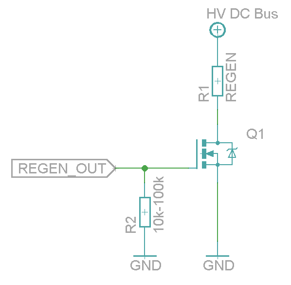
| REGEN_OUT | Regenerative resistor control output | Use to control optional regenerative resistor to prevent excessive voltage generation in HV DC bus during motor deceleration. | A buffer circuit is needed for resistor, such as a logic level MOSFET. See example schematic here. |
| MECH_BRAKE_OUT | Mechanical holding brake control output | Use to control optional holding brake of motor | A buffer circuit is needed to drive a solenoid brake, such as a logic level MOSFET. See example schematic here. |
| ENABLE_IN | Drive enable input signal (always required) | Use to enable drive and allow motor to initialize and operate | Accepts up to 24V voltage level, but works also with 5V level signal. (1) |
| STO2 | Safe torque off input signal (always required) | Use to allow motor to produce torque (activate power stage) | Accepts up to 24V voltage level, but works also with 5V level signal. STO is inactive (allows torque) when logic high is supplied. (1) |
(1) ENABLE_IN and STO2 are not 3.3V compatible, 4.5-26V signal is required to drive logic true state into them.
Electrical ratings[edit | edit source]

| Signal names | Allowed input voltages/output voltage | Internal input/output impedance (Ω) | Internal pull impedance (Ω) |
|---|---|---|---|
| 5V_IN | 5V +/-10% | - | - |
| HV+ | 0 – 55 V | - | - |
| RS485_A/B | RS485 serial bus, 2.7-5.5V signal level | >10k | - |
| ADDRSEL1, ADDRSEL2 | External address setting pull-down resistors to ground (minimum 1 kΩ). See chapter Selecting device address below. | - | 2.2k pull-up to 3.3V |
| HSIN1, HSIN2 | Logic low -0.3-1.0V, logic high 2.7-5.5V | - | 2.2k pull-up to 3.3V |
| ANAIN-, ANAIN+ | +/- 11V | 8k | - |
| GPI1...GPI4 | Logic low -0.3-1.0V, logic high 2.7-5.5V | - | 2.2k pull-up to 5V |
| GPI5 | Logic low -0.3-1.0V, logic high 2.7-5.5V | - |
|
| GPO1,2,4,5 | Logic low 0V, logic high 3.3V | 220 | - |
| GPO3 | Depends on Electrical interface Electrical interfaceCEI parameter: In IONICUBE mode it is an open drain output, pulled to 0V with 220 ohm impedance or pulled to 3.3V with pull-up (allow wired and connection of multiple drives). In other modes it is push-pull output (like GPO1,2,4,5) | 220 | ~20-50k pull-up to 3.3V |
| MECH_BRAKE_OUT | Logic low 0V, logic high 3.3V | 220 | - |
| REGEN_OUT | Logic low 0V, logic high 3.3V | 220 | - |
| ENABLE_IN | Logic low -0.3-2.0V, logic high 4.5-26V | 5k | 10k pull-down to GND |
| STO2 | Logic low -0.3-2.0V, logic high 4.5-26V | 8k | 20k pull-down to GND |
| HALL_U/V/W | Logic low -0.3-1.0V, logic high 2.7-5.5V | - | 2.2k pull-up to 5V |
| A/B/C+ | RS422 receiver, 2.7-5.5V signal level | - | 2.2k pull-up to 5V |
| A/B/C- | RS422 receiver, 2.7-5.5V signal level | - | 1.9k pull to 1.9V |
Electrical interface modes (software selectable)[edit | edit source]
IONI supports various function mappings to I/O signals and is selectable through Granity CEI Electrical interface parameter. The differences between modes are:
| Mode | Description | Effects (change of operation compared to Standard in this mode) |
|---|---|---|
| Standard | The default mode | I/O assignments as described in pinout |
| IONICUBE (CNC applications) | Mode for IONICUBE that is compatible with parallel port CNC controllers such as Mach3 and LinuxCNC software.
Not recommended with IONICUBE 1X as GPO3/fault output will not work then. |
|
| SimuCUBE | Mode for SimuCUBE motherboard for force feedback simulator systems. |
|
Selecting device address[edit | edit source]
When accessing drive through SimpleMotion V2 bus, each device in the bus should be assigned to different address between 1 to N. Device address is a sum of hardware setting and software parameter SimpleMotion bus address offsetSMO. The address of device is determined at the moment of logic voltage power on and will become by sum of hardware setting and SMO.
Hardware setting is set by connecting a resistor between ADDRSELx and GND by method defined in article IONI SimpleMotion address selection (ADDRSEL).
Software selecting address[edit | edit source]
When having more than four devices in the same bus, or for example chaining multiple IONICUBE 1X motherboards (where all of them have address 1), it is necessary to utilize software parameter SimpleMotion bus address offsetSMO. Procedure for setting unique address for each device with SMO:
- Disconnect or unpower all other devices that the ones with already unique address (i.e. have only one IONICUBE connected to SM bus, or powered on)
- Connect to drive with Granity
- Adjust SMO parameter value so that device will receive a desired bus address. I.e. if using IONICUBE 1X, set SMO values 0, 1, 2, 3 to the different drives (drive addresses will become 1, 2, 3, 4). Or when IONICUBE (4 axis) is being used, set SMO values of drives on the first board 0, second board 4, third 8 etc (drive addresses will become 1 - 12).
- Save settings, disconnect and repeat the procedure for all drives.
In no event the Product Information or parts hereof shall be regarded as guarantee of conditions or characteristics. The Product Information or any part thereof may also not be regarded as a warranty of any kind. No liability of any kind shall be assumed by Author with respect to Product Information or any use made by you thereof, nor shall Author indemnify you against or be liable for any third party claims with respect to such information or any use thereof.
As content of this Wiki may be edited by user community, Granite Devices Oy or it's affiliates do not take any responsibility of the contents of this Wiki. Use information at your own risk. However, Granite Devices staff attempts to review all changes made to this Wiki and keep information trustworthy.
Without written consent, Granite Devices' Products or Intellectual Property shall not be used in situations or installations where living beings, material property, or immaterial property could be harmed by the operation, features or failures of Product. Products may only be used in a way where hazards like moving parts, electric shock, laser radiation, or fire can't be realized even if the content of this Wiki would suggest otherwise.