Difference between revisions of "IONICUBE 1X connectors and pinouts"
| [checked revision] | [checked revision] |
(→Dimensions and mounting) |
|||
| Line 190: | Line 190: | ||
==Dimensions and mounting== | ==Dimensions and mounting== | ||
| − | IONICUBE 1X can be mounted by screws to a base or with optional DIN rail clips to a standard DIN rail. To mount in DIN rail, obtain 2 pcs of Phoenix Contact part number 1201578. Such part is available from many distributors including {{digikey|277-2296-ND}} | + | IONICUBE 1X can be mounted by screws to a base or with optional DIN rail clips to a standard DIN rail. |
| + | |||
| + | To mount in DIN rail, obtain 2 pcs of Phoenix Contact part number 1201578. Such part is available from many distributors including {{digikey|277-2296-ND}} | ||
{{picturebox|Ionicube1x dims.png|caption=Dimensions and mounting hole locations}}. | {{picturebox|Ionicube1x dims.png|caption=Dimensions and mounting hole locations}}. | ||
[[category:IONI user guide]] | [[category:IONI user guide]] | ||
[[category:IONICUBE]] | [[category:IONICUBE]] | ||
Revision as of 12:55, 13 May 2015
Contents
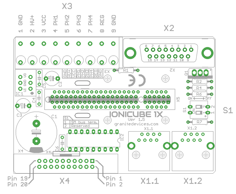
IONICUBE 1X connectors
- X1.1 and X1.2
- RJ45 connector with SimpleMotion V2 interface. For pinout, seeSimpleMotion V2 port.
- X2
- feedback device connector for motor
- X3
- 9 pin wire terminal for HV DC bus supply, logic voltage supply, regenerative resistor and motor power output.
- X4
- Control and setpoint signal port. Contains also output for motor solenoid holding brake.
- X5
- Card-edge connectors for IONI drive
| Before inserting or removing IONI drives from IONICUBE, remove all power from it and discharge it's capacitors. To discharge remaining energy (~voltage) from capacitors, short circuit GND to HV+ by a conductor and measure that there is no DC voltage left between GND and HV+ terminals. Even few volts left to HV DC bus is known to cause permanent damage to IONICUBE when drives are plugged. |
IONICUBE 1X connectors
Legend
| Color |
|---|
| Supply pin |
| Input pin |
| Output pin |
X3 pinout
This is a wire terminal connector for power input and output
| Pin number | Signal name | Usage |
|---|---|---|
| 1 | GND | Ground |
| 2 | HV+ | Motor power supply, HV DC bus (see IONI drive voltage range spec) |
| 3 | VCC | 24V logic supply |
| 4 | PH1 (PHASE1) | Motor phase 1 |
| 5 | PH2 (PHASE2) | Motor phase 2 |
| 6 | PH3 (PHASE3) | Motor phase 3 |
| 7 | PH4 (PHASE4) | Motor phase 4 |
| 8 | REG | Regenerative resistor output |
| 9 | GND | Ground |
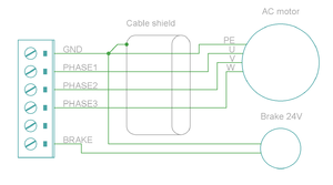
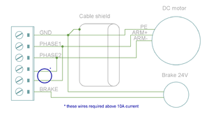
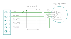
Motor & brake wiring schematics
Note: the images below are drawn for IONICUBE 4 axis version. IONICUBE 1X wiring is equivalent except there is no brake output in the X3. Brake output pin is located in X4.
X2 pinout
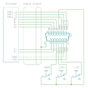
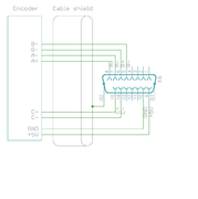
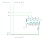
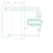
X2 is the feedback device connector of motor
| Pin # | Pin name | Electrical type (in most feedback device modes) | Alternate electrical type (in some feedback device modes) | Connection with various feedback devices |
|---|---|---|---|---|
| Shell | GND | Earth/case | Feedback cable shield | |
| 1 | HALL_W | Digital input W | Hall sensor input, phase W | |
| 2 | HALL_V | Digital input V | Hall sensor input, phase V | |
| 3 | HALL_U | Digital input U | Hall sensor input, phase U | |
| 4 | GND | Encoder supply ground | ||
| 5 | B- | Differential input B- | Analog input B+ | Quadrature encoder (B channel)/SinCos/serial encoder/resolver input |
| 6 | B+ | Differential input B+ | Analog input B- | |
| 7 | A- | Differential input A- | Analog input A- | Quadrature encoder (A channel)/SinCos/serial encoder/resolver input |
| 8 | A+ | Differential input A+ | Analog input A+ | |
| 9 | 5V_OUT | Encoder supply 5V output | Encoder power supply | |
| 10 | GND | Encoder supply ground | ||
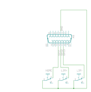
| 11 | GPI3 | Axis negative direction end limit switch (optional) | Connect normally closed (NC) limit switch between this pin and GND pin | |
| 12 | GPI2 | Axis positive direction end limit switch (optional) | Connect normally closed (NC) limit switch between this pin and GND pin | |
| 13 | GPI1 | Axis home switch switch (optional) | Connect normally closed (NC) limit switch between this pin and GND pin | |
| 14 | C- | Differential input C- | Quadrature encoder index channel (Z channel)/serial encoder input | |
| 15 | C+ | Differential input C+ | ||
Examples of feedback device and switch wiring
| In case of single-ended encoder, connect encoder's A, B, Z only to drive's A+, B+ and C+ and leave drive's A-, B- and C- unconnected. |
| With differential Hall sensor (which provides U+, U-, V+, V-, W+ and W-, connect only sensor's U+, V+ and W+ to drive's HALL_U/V/W. |
| Never connect sensor negative outputs (A-/B-/C-/U-/V-/W-) to GND. Connect them to drive's A-/B-/C- or leave unconnected. |
| Feedback devices with differential signaling may use varying naming schemes of signal pairs. For example differential signal X (which contains two electrical wires) may be denoted as: X+ and X-, or X and \X or X and X. In this Wiki we mark them X+ and X-. Some Fanuc encoders have quadrature signals named as PCA, /PCA, PCB, /PCB, PCZ and /PCZ which are equivalent to A, B and Z signal pairs. |
X1 connector
X1 connectors are for SimpleMotion V2 bus which is used for drive configuration with Granity software and control over a multidrop capable serial data link.
| Never connect an Ethernet to X1. While it uses similar connector and cabling, it is electrically incompatible with Ethernet. Devices may be permanently damaged by mixing Ethernet and SimpleMotion V2. |
| Do now wire SimpleMotion V2 ports with crossover RJ45 cables (see details). Always use straight/non-crossover patch cables. If unsure about what is the type of your RJ45 cable, don't use it. |
X4 pinout
| This section is unfinished. Don't use until this notice is removed. |
X4 is main control and setpoint signal port consisting Enable input signal, Fault output signal, pulse and direction/quadrature/PWM setpoint inputs and digital outputs for home switch status. X4 is directly wired to conform most common parallel port style pulse & direction CNC controllers.
| Pin number in header | Pin number in D25 cable | Signal name | Typical usage | Pin number in header | Pin number in D25 cable | Signal name | Typical usage | |
|---|---|---|---|---|---|---|---|---|
| 1 | 1 | ENABLE | Enable all axis (with or without chargepump) | 2 | 14 | PWM | PWM input for VFD analog output | |
| 3 | 2 | HSIN1_X | Direction input X | 4 | 15 | GPO4_A | Limit switch output A | |
| 5 | 3 | HSIN2_X | Pulse/step input X | 6 | 16 | RLIN1 | Controls RL1 state | |
| 7 | 4 | HSIN1_Y | Direction input Y | 8 | 17 | RLIN2 | Controls RL2 state | |
| 9 | 5 | HSIN2_Y | Pulse/step input Y | 10 | 18 | GND | Ground | |
| 11 | 6 | HSIN1_Z | Direction input Z | 12 | 19 | GND | ||
| 13 | 7 | HSIN2_Z | Pulse/step input A | 14 | 20 | GND | ||
| 15 | 8 | HSIN1_A | Direction input A | 16 | 21 | GND | ||
| 17 | 9 | HSIN2_A | Pulse/step input A | 18 | 22 | GND | ||
| 19 | 10 | STOP_OUT | Fault on any axis or E-stop (active low) | 20 | 23 | GND | ||
| 21 | 11 | GPO4_X | Limit switch output X | 22 | 24 | GND | ||
| 23 | 12 | GPO4_Y | Limit switch output Y | 24 | 25 | GND | ||
| 25 | 13 | GPO4_Z | Limit switch output Z | 26 | N/A | Not connected |
| Connect X4/X5 only to 3.3V or 5V logic systems. For 24V logic the use of IONICUBE 1X is recommended |
X5 is a second control and setpoint signal port in addition to X4. This port consists analog setpoint signal inputs and additional digital I/O.
| Pin number in header | Pin number in D25 cable | Signal name | Typical usage | Pin number in header | Pin number in D25 cable | Signal name | Typical usage | |
|---|---|---|---|---|---|---|---|---|
| 1 | 1 | GND | 2 | 14 | +5V_OUT | 5V supply from IONICUBE ^2 | ||
| 3 | 2 | ANAIN-_X | +/-10V analog input X | 4 | 15 | ANAIN+_X | +/-10V analog input X | |
| 5 | 3 | ANAIN-_Y | +/-10V analog input Y | 6 | 16 | ANAIN+_Y | +/-10V analog input Y | |
| 7 | 4 | ANAIN-_Z | +/-10V analog input Z | 8 | 17 | ANAIN+_Z | +/-10V analog input Z | |
| 9 | 5 | ANAIN-_A | +/-10V analog input A | 10 | 18 | ANAIN+_A | +/-10V analog input A | |
| 11 | 6 | GPO1_X | For pin function, refer to IONI connector pinout | 12 | 19 | GPI4_X | For pin function, refer to IONI connector pinout | |
| 13 | 7 | GPO1_Y | 14 | 20 | GPI4_Y | |||
| 15 | 8 | GPO1_Z | 16 | 21 | GPI4_Z | |||
| 17 | 9 | GPO1_A | 18 | 22 | GPI4_A | |||
| 19 | 10 | GPO5_X | 20 | 23 | GPI5_X | |||
| 21 | 11 | GPO5_Y | 22 | 24 | GPI5_Y | |||
| 23 | 12 | GPO5_Z | 24 | 25 | GPI5_Z | |||
| 25 | 13 | GPO5_A | 26 | N/A | GPI5_A |
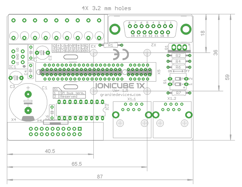
Dimensions and mounting
IONICUBE 1X can be mounted by screws to a base or with optional DIN rail clips to a standard DIN rail.
To mount in DIN rail, obtain 2 pcs of Phoenix Contact part number 1201578. Such part is available from many distributors including Digikey 277-2296-ND
.