Argon user guide/Wiring
This article state is work in progress & unchecked! Use at your own risk.
Contents
Front connectors
J3 24V power and motor brake port
J3 is a 3 pole terminal block type connector used for supplying 24VDC to drive and optionally controlling motor solenoid brake.
| Pin | Description | Connection |
|---|---|---|
| BK | Motor brake output | If motor has a 24V solenoid brake, connect brake between BK and V+ |
| V+ | 24V supply positive input | Connect to 24V PSU + |
| V- | 24V supply ground | Connect to 24V PSU - |
24VDC typical current consumption is between 0.1 - 0.7ADC depending on how much current is drawn by feedback device and an optional motor brake.
J1 feedback device port
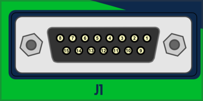
J1 connector type is 15 pin female D-Sub and should be mated with 15 pin male D-Sub counterpart.
J1 pinout is to be announced later.
J2.1 and J2.2 Simplemotion & E-stop ports
J2.1 and J2.2 are RJ45 type connectors and mates with standard Cat 5 & 6 ethernet cables. Both of these ports are connected pin-to-pin parallel to allow chaining of Argon devices. For J2.x pinout, see SimpleMotion V2 port article.
Normally an ethernet type cable is plugged from J2.1 or J2.2 to SimpleMotion V2 USB adapter
J4 power & motor port
J4 is a 10 pole terminal block connector for several functions: earthing, AC power input, motor output, regenerative resistor output and HV DC link sharing.
| dangerous & non-isolated mains potential voltages are present in this connector! Keep away from this connector when drive has been connected to AC mains during last 5 minutes. After unplugging AC power, 5 minutes is required for dangerous voltages to disappear from this connector. For more info, see Power supply safe discharging |
| Pin name | Descrpition | AC/BLDC motor connection | Brush DC motor connection |
|---|---|---|---|
| VN | HV DC link negative rail | Do not connect | |
| BR | Braking resistor output | Optional braking resistor first terminal. See Argon braking resistor | |
| VP | HV DC link positive rail | Optional braking resistor first terminal. See Argon braking resistor | |
| PE ⏚ | Protective earth | Connect to motor PE conductor and motor cable shield | |
| U | Motor phase output | Motor U phase ¹ | Motor armature+ |
| V | Motor phase output | Motor V phase ¹ | Motor armature- |
| W | Motor phase output | Motor W phase ¹ | No connection |
| L | AC mains supply Line | Connect to AC supply line | |
| N | AC mains supply Neutral | Connect to AC supply neutral | |
| PE ⏚ | Protective earth | Connect to supply protective earth. This connection is always mandatory when any voltage larger than 30 VAC or 42 VDC is supplied to the device! | |
¹ In some motors U,V,W phases are called R,S,T instead.
Side connectors
J5 Inputs/Outputs
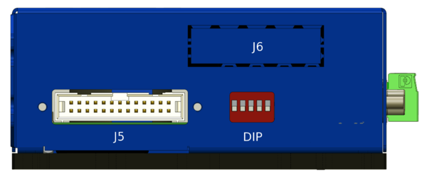
J5 Is a 26 pin IDC connector located on the side of Argon. The connector serves as general purpose I/O including:
- Isolated digital inputs (4 pcs) - used for limit & home switches and clear faults signal
- Isolated digital outputs (4 pcs) - used for status indication
- Differential analog inputs (2 pcs) - used as Analog reference
- Differential digital inputs (2 pcs) - used for pulse/direction or second encoder
- 5V and GND output - used for supplying switches or external electronics
Mating connector type is 0.1" pitch 26 pin IDC ribbon cable socket, see example (pdf).
Pin-out
Please see Argon I/O connector electrical interfacing before wiring to this port.
| Pin # | Pin name | Electrical | Isolated | Function¹ |
|---|---|---|---|---|
| 1 | GND | Supply | No² | Ground |
| 2 | +5V_OUT | Supply | 5V output | |
| 3 | HSIN1- | High speed digital input | Pulse train, Quadrature or PWM input reference | |
| 4 | HSIN1+ | High speed digital input | ||
| 5 | HSIN2- | High speed digital input | Future use (i.e. secondary feedback device) | |
| 6 | HSIN2+ | High speed digital input | ||
| 7 | ANAIN1- | Analog input | Analog input reference | |
| 8 | ANAIN1+ | Analog input | ||
| 9 | ANAIN2- | Analog input | Future use (i.e. secondary feedback device) | |
| 10 | ANAIN2+ | Analog input | ||
| 11 | GPO1- | Digital output | Yes² | Servo ready status. True when drive is initialized and ready to accept user commands/reference. |
| 12 | GPO1+ | Digital output | ||
| 13 | GPO2- | Digital output | Follow error warning status. True when following error has reached more than user configured 1/8 of fault limit value. | |
| 14 | GPO2+ | Digital output | ||
| 15 | GPO3- | Digital output | Fault stop status. True when drive is stopped due to fault. | |
| 16 | GPO3+ | Digital output | ||
| 17 | GPO4- | Digital output | Braking status. Set true when drive attempts to brake motor. | |
| 18 | GPO4+ | Digital output | ||
| 19 | GPI1- | Digital input | Home switch input. | |
| 20 | GPI1+ | Digital input | ||
| 21 | GPI2- | Digital input | Positive feed enable input. Used for axis limit switches. | |
| 22 | GPI2+ | Digital input | ||
| 23 | GPI3- | Digital input | Negative feed enable input. Used for axis limit switches. | |
| 24 | GPI3+ | Digital input | ||
| 25 | GPI4- | Digital input | Clear drive faults input. Transition from false to true attempts to reset active faults of drive. If drive is simultaneously in enabled state, motor will start moving immediately. | |
| 26 | GPI4+ | Digital input |
¹) This is the default function with stock firmware. Function may be different in future or custom firmware versions.
²) Non-isolated lines are referenced to GND pin / J3 V- terminal. Isolated lines have functional isolation between GND and other isolated +-/- pairs.
J6 Expansion slot
This slot is reserved for Argon add-on card that may be installed inside the drive.
DIP Switches
DIP switches serves as address selector when connecting the drive to SimpleMotion V2 bus or Granity.
Mating parts
See list of Argon mating connectors and accessories
In no event the Product Information or parts hereof shall be regarded as guarantee of conditions or characteristics. The Product Information or any part thereof may also not be regarded as a warranty of any kind. No liability of any kind shall be assumed by Author with respect to Product Information or any use made by you thereof, nor shall Author indemnify you against or be liable for any third party claims with respect to such information or any use thereof.
As content of this Wiki may be edited by user community, Granite Devices Oy or it's affiliates do not take any responsibility of the contents of this Wiki. Use information at your own risk. However, Granite Devices staff attempts to review all changes made to this Wiki and keep information trustworthy.
Without written consent, Granite Devices' Products or Intellectual Property shall not be used in situations or installations where living beings, material property, or immaterial property could be harmed by the operation, features or failures of Product. Products may only be used in a way where hazards like moving parts, electric shock, laser radiation, or fire can't be realized even if the content of this Wiki would suggest otherwise.


