Difference between revisions of "Commissioning of KANZ servo motors"
| [checked revision] | [checked revision] |
m (Text replacement - "\[\[([A-Z]{2,3})\]\]" to "{{param|$1}}") |
|||
| (19 intermediate revisions by the same user not shown) | |||
| Line 1: | Line 1: | ||
| − | [[File: | + | [[File:Kanz10wires_m.JPG|thumb|KANZ series servo motor with premade cables]]This article gives tips for fast-forward installation of KANZ series [[Granite Devices servo motors]] on [[Argon]] servo drive. However, this article is not complete user guide for Argon, so user must be already familiar with operation of the drive or follow [[Argon user guide]] simultaneously. |
| − | [[File:Kanz termination.jpg| | + | ==Wiring== |
| − | + | ===Wire preparation=== | |
| − | [[File: | + | KANZ motors come with pre-assembled cables for Argon servo drive (encoder and motor part). However, some motor models include excessive 4-pin terminal for motor part that needs to be stripped away. |
| − | [[Media:KANZ Argon base settings.zip]] | + | <gallery widths="240px" heights="240px"> |
| + | File:Kanz termination.jpg|The excessive 4-pin connector that need to be cut away. Stripping 3-5 cm of black outer insulation is recommended to make space for [[EMI suppression cores]]. | ||
| + | File:Kanz termination2.jpg|Strip wire ends. Cutting U,V,W 1-2 cm shorter than PE is recommended for safety (to make PE the last to disconnect if cable pulled by force). | ||
| + | File:Kanz termination3.jpg|Optional, but recommended, ferrule crimping of wire ends. | ||
| + | File:Kanz termination4.jpg|Minimum length of wire ends to fit single EMI suppression core to leads. Note: it recommended to strip outer insulation before crimping. | ||
| + | </gallery> | ||
| + | {{electricshock|Ensure that insulation of inner wires have not been damaged in the process of wire stripping and that there is no loose wire strands }} | ||
| + | ===Connecting=== | ||
| + | First, ensure that you have understood [[Argon user guide/Wiring|Argon user guide wiring section]] and especially [[Argon user guide/Earthing|earthing section]] before proceeding with installation. | ||
| + | |||
| + | Pre-made encoder cable plugs directly into Argon J1 connector and motor U, V, W and PE connect to J4 terminal to their respective positions. Insert [[EMI suppression cores]] as illustrated below: | ||
| + | |||
| + | [[File:Argon wired to KANZ annotated.jpg|800px]] | ||
| + | |||
| + | ==Parameterization== | ||
| + | For parameterization, make sure you understand [[Argon_user_guide/Drive_parameterization|Argon drive parameterization]] basics. To speed up commissioning of motor, pre-made base configuration files are provided for stocked servo motors. Instructions for using the files: | ||
| + | {{warning|When loading settings, have drive disconnected from AC power for safety reasons. Ensure that all settings and wirings (including emergency stopping) are ready before connecting AC power.}} | ||
| + | #Download KANZ motor configuration files: [[Media:KANZ Argon base settings.zip]] | ||
| + | #Connect drive to Granity ([[Argon_user_guide/Making_the_first_Granity_connection|instructions]]) | ||
| + | #Click ''Load settings from file'' and open corresponding configuration file. Choose the file that is most has similar beginning with motor mode (i.e. KANZ04... file for KANZ-04BF8N2 motor). | ||
| + | #Click ''Save settings on drive non-volatile memory'' and if choose Apply and Restart drive buttons in the dialogs that may appear | ||
| + | #After drive restarts, connect again to drive and review all settings. For first testing safety it is recommended to reduce current limits {{param|MMC}} and {{param|MCC}} to a lower value (such as 20% of rated values) in order to limit motor torque if unexpected motion takes place. Also set control mode {{param|CM}} as required by end application. | ||
| + | #After all Ok, click ''Apply settings'' and you're ready to connect AC power for first tests. | ||
| + | #Go to Testing page and begin motor tuning according to [[Servo motor tuning guide]] | ||
| + | |||
| + | {{tip|Pre-made motor configuration files may have significantly different motor resistance {{param|MR}} and inductance {{param|ML}} values compared to motor data sheet. Pre-made files are hand-optimized to give better performance than entering values from data sheet, so it is recommended to leave these values untouched.}} | ||
| + | |||
| + | [[category:Argon user guide]] | ||
Latest revision as of 19:54, 28 August 2015
This article gives tips for fast-forward installation of KANZ series Granite Devices servo motors on Argon servo drive. However, this article is not complete user guide for Argon, so user must be already familiar with operation of the drive or follow Argon user guide simultaneously.
Wiring[edit | edit source]
Wire preparation[edit | edit source]
KANZ motors come with pre-assembled cables for Argon servo drive (encoder and motor part). However, some motor models include excessive 4-pin terminal for motor part that needs to be stripped away.
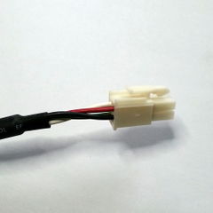
The excessive 4-pin connector that need to be cut away. Stripping 3-5 cm of black outer insulation is recommended to make space for EMI suppression cores.
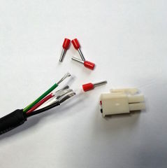
Strip wire ends. Cutting U,V,W 1-2 cm shorter than PE is recommended for safety (to make PE the last to disconnect if cable pulled by force).

Optional, but recommended, ferrule crimping of wire ends.

Minimum length of wire ends to fit single EMI suppression core to leads. Note: it recommended to strip outer insulation before crimping.


| Ensure that insulation of inner wires have not been damaged in the process of wire stripping and that there is no loose wire strands |
Connecting[edit | edit source]
First, ensure that you have understood Argon user guide wiring section and especially earthing section before proceeding with installation.
Pre-made encoder cable plugs directly into Argon J1 connector and motor U, V, W and PE connect to J4 terminal to their respective positions. Insert EMI suppression cores as illustrated below:

Parameterization[edit | edit source]
For parameterization, make sure you understand Argon drive parameterization basics. To speed up commissioning of motor, pre-made base configuration files are provided for stocked servo motors. Instructions for using the files:
| When loading settings, have drive disconnected from AC power for safety reasons. Ensure that all settings and wirings (including emergency stopping) are ready before connecting AC power. |
- Download KANZ motor configuration files: Media:KANZ Argon base settings.zip
- Connect drive to Granity (instructions)
- Click Load settings from file and open corresponding configuration file. Choose the file that is most has similar beginning with motor mode (i.e. KANZ04... file for KANZ-04BF8N2 motor).
- Click Save settings on drive non-volatile memory and if choose Apply and Restart drive buttons in the dialogs that may appear
- After drive restarts, connect again to drive and review all settings. For first testing safety it is recommended to reduce current limits Peak current limitMMC and Continuous current limitMCC to a lower value (such as 20% of rated values) in order to limit motor torque if unexpected motion takes place. Also set control mode Control modeCM as required by end application.
- After all Ok, click Apply settings and you're ready to connect AC power for first tests.
- Go to Testing page and begin motor tuning according to Servo motor tuning guide
| Pre-made motor configuration files may have significantly different motor resistance Coil resistanceMR and inductance Coil inductanceML values compared to motor data sheet. Pre-made files are hand-optimized to give better performance than entering values from data sheet, so it is recommended to leave these values untouched. |