Difference between revisions of "IONICUBE 1X"
From Granite Devices Knowledge Wiki
| [checked revision] | [checked revision] |
(→Applications) |
|||
| (9 intermediate revisions by the same user not shown) | |||
| Line 1: | Line 1: | ||
{{Infobox drive | {{Infobox drive | ||
| name = IONICUBE 1X | | name = IONICUBE 1X | ||
| − | | image=[[File: | + | | image=[[File:ionicube1x.jpg|290px]] |
| modelno = IONICUBE 1X | | modelno = IONICUBE 1X | ||
| drivetype = Single axis motherboard for [[IONI]] drives | | drivetype = Single axis motherboard for [[IONI]] drives | ||
| − | | motors = AC, DC, BLDC, Linear | + | | motors = AC, DC, BLDC, Linear, Stepper |
| controlmodes = Position, Velocity, Torque | | controlmodes = Position, Velocity, Torque | ||
| voltage= Same as [[IONI]] specifications | | voltage= Same as [[IONI]] specifications | ||
| Line 10: | Line 10: | ||
| agencies=CE (EMC & LVD directives) | | agencies=CE (EMC & LVD directives) | ||
| 3dmodel=TBA | | 3dmodel=TBA | ||
| + | | url=[https://granitedevices.com/ionicube-multiaxis-servo-drive-boards/ Granite Devices IONICUBE] | ||
| + | |||
}}{{IoniManualNav|width=22em|notoc=1}} | }}{{IoniManualNav|width=22em|notoc=1}} | ||
| Line 19: | Line 21: | ||
*Support mechanical end-of-travel switches and homing switch | *Support mechanical end-of-travel switches and homing switch | ||
*Motor holding brake output with driver | *Motor holding brake output with driver | ||
| − | * | + | *20 pin ribbon cable connector for I/O and [[setpoint]] signals |
*Support 3.3V, 5V and 24V<sup>1</sup> I/O signal levels | *Support 3.3V, 5V and 24V<sup>1</sup> I/O signal levels | ||
| − | *Charge | + | *[[Charge pump enable input]] for safety |
| − | *E-stop switch input (safe torque off) | + | *E-stop switch input ([[safe torque off]]) |
| − | *[[ARGON Servo Drive]] compatible encoder connector pin-out | + | *[[IONICUBE]] and [[ARGON Servo Drive]] compatible encoder connector pin-out |
*RJ45 connectors for SimpleMotion V2 usage and configuration | *RJ45 connectors for SimpleMotion V2 usage and configuration | ||
*On-board 0.5A 5V regulator to power drive logic and [[feedback devices]] | *On-board 0.5A 5V regulator to power drive logic and [[feedback devices]] | ||
*DIN rail mounting option | *DIN rail mounting option | ||
| + | |||
| + | ==Applications== | ||
| + | *Distributed drive systems | ||
| + | *Industrial automation | ||
| + | *Robotics | ||
<sup>1</sup>) 24V I/O needs external components in certain cases | <sup>1</sup>) 24V I/O needs external components in certain cases | ||
| + | |||
==User guide== | ==User guide== | ||
| + | * [[IONICUBE 1X electrical specifications]] | ||
* [[IONI & IONICUBE user guide]] | * [[IONI & IONICUBE user guide]] | ||
* [[IONICUBE 1X connectors and pinouts]] | * [[IONICUBE 1X connectors and pinouts]] | ||
| Line 35: | Line 44: | ||
==See also== | ==See also== | ||
* [[IONICUBE]] - 4 axis motherboard for IONI | * [[IONICUBE]] - 4 axis motherboard for IONI | ||
| − | [[ | + | |
| − | [[ | + | [[Category:Hardware]] |
| + | [[Category:IONICUBE]] | ||
Latest revision as of 11:28, 27 March 2018
| IONICUBE 1X | |
|---|---|
 | |
| Device type | Single axis motherboard for IONI drives |
| Model number | IONICUBE 1X |
| Supported motors | AC, DC, BLDC, Linear, Stepper |
| Control modes | Position, Velocity, Torque |
| Status | Active production, started 2015 |
| Electrical | |
| DC supply voltage | Same as IONI specifications |
| General | |
| Web site | Granite Devices IONICUBE |
| Compliance | CE (EMC & LVD directives) |
| 3D model |
TBA |
Contents
Features[edit | edit source]
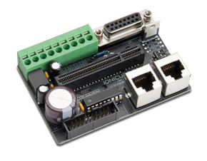
IONICUBE 1X has been designed robotics and automation systems in mind. On-board features include:
- Carry single IONI drive
- On-board regenerative braking resistor drive (need just an external resistor)
- Support mechanical end-of-travel switches and homing switch
- Motor holding brake output with driver
- 20 pin ribbon cable connector for I/O and setpoint signals
- Support 3.3V, 5V and 24V1 I/O signal levels
- Charge pump enable input for safety
- E-stop switch input (safe torque off)
- IONICUBE and ARGON Servo Drive compatible encoder connector pin-out
- RJ45 connectors for SimpleMotion V2 usage and configuration
- On-board 0.5A 5V regulator to power drive logic and feedback devices
- DIN rail mounting option
Applications[edit | edit source]
- Distributed drive systems
- Industrial automation
- Robotics
1) 24V I/O needs external components in certain cases
User guide[edit | edit source]
See also[edit | edit source]
- IONICUBE - 4 axis motherboard for IONI