Difference between revisions of "SimuCUBE LED indicators"
From Granite Devices Knowledge Wiki
| [checked revision] | [checked revision] |
(→SimuCUBE LED indicators) |
m (→SimuCUBE LED indicators) |
||
| Line 17: | Line 17: | ||
|Lit when on board 3.3V signal power is on | |Lit when on board 3.3V signal power is on | ||
|- | |- | ||
| − | | LED4 || Green || Firmware | + | | LED4 || Green || MMOS: Clipping led. SimuCUBE Firmware: Clipping led. |
|Connected to STM32F4 I/O pin PD15. | |Connected to STM32F4 I/O pin PD15. | ||
|- | |- | ||
| Line 23: | Line 23: | ||
|Connected to STM32F4 I/O pin PD14 | |Connected to STM32F4 I/O pin PD14 | ||
|- | |- | ||
| − | | | + | | LED6 || Green || Firmware controlled, TBA |
|Connected to STM32F4 I/O pin PD13 | |Connected to STM32F4 I/O pin PD13 | ||
|} | |} | ||
Latest revision as of 13:20, 28 February 2018
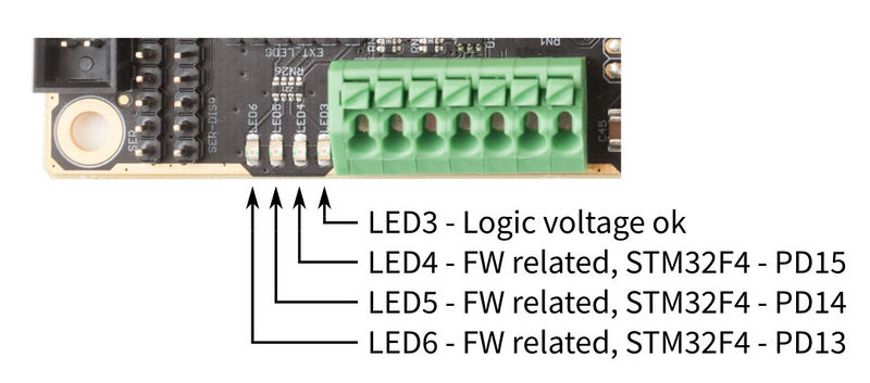
SimuCUBE system has two sets of leds: one set on SimuCUBE board and another set in the plugged IONI drive.IONI[edit | edit source]
For IONI LED status indicators, please refer to IONI LED indicators.
SimuCUBE[edit | edit source]
SimuCUBE LED indicators[edit | edit source]
| LED # | Color | Indication | Technical information |
|---|---|---|---|
| LED3 | Green | Power on | Lit when on board 3.3V signal power is on |
| LED4 | Green | MMOS: Clipping led. SimuCUBE Firmware: Clipping led. | Connected to STM32F4 I/O pin PD15. |
| LED5 | Red | Firmware controlled, TBA | Connected to STM32F4 I/O pin PD14 |
| LED6 | Green | Firmware controlled, TBA | Connected to STM32F4 I/O pin PD13 |
