Difference between revisions of "SimuCUBE pinouts and wiring"
| [checked revision] | [checked revision] |
(Created page with "{{SimucubeManualNav}} ==External connectors== Overview of external SimuCUBE connectors. ===Legend=== {| class="wikitable" |...") |
m (→External connectors) |
||
| Line 127: | Line 127: | ||
Pin 1 is the right-most.<br> | Pin 1 is the right-most.<br> | ||
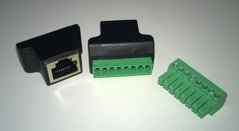
Use with a RJ45 (8P8C) modular connector. Can be used with straight unshielded or shielded CAT3/5/5e cables (<b>don't</b> use crossover cables!) | Use with a RJ45 (8P8C) modular connector. Can be used with straight unshielded or shielded CAT3/5/5e cables (<b>don't</b> use crossover cables!) | ||
| + | Note: These analog inputs are 3.3 V tolerant. Do not connect 5 V signals. | ||
{| class="wikitable" | {| class="wikitable" | ||
|- | |- | ||
| Line 151: | Line 152: | ||
Pin 1 is the left-most.<br> | Pin 1 is the left-most.<br> | ||
Use with a RJ45 (8P8C) modular connector. Can be used with straight unshielded or shielded CAT3/5/5e cables (<b>don't</b> use crossover cables!) | Use with a RJ45 (8P8C) modular connector. Can be used with straight unshielded or shielded CAT3/5/5e cables (<b>don't</b> use crossover cables!) | ||
| + | Note: These analog inputs are 3.3 V tolerant. Do not connect 5 V signals. | ||
{| class="wikitable" | {| class="wikitable" | ||
|- | |- | ||
Revision as of 12:39, 28 February 2018
External connectors
Legend
| Color |
|---|
| Supply pin |
| Input pin |
| Output pin |
X1 - Motor & E-stop connector
| Pin number | Signal name | Usage |
|---|---|---|
| 1 | U / PH1 | Motor phase 1 / Servo U |
| 2 | V / PH2 | Motor phase 2 / Servo V |
| 3 | W / PH3 | Motor phase 3 / Servo W |
| 4 | PH4 | Motor phase 4 |
| 5 | GND | Ground voltage (0 V) of the SimuCUBE, shield |
| 6 | E-Stop / STO | External stop / Safe Torque Off input pin (active high) |
| 7 | +5 V | 5 V supply voltage |
X16 - Motor position sensor connector
A, B, and C indicate the quadrature encoder differential signals.
| Pin # | Pin name | Electrical type (in most feedback device modes) |
|---|---|---|
| Shell | GND | Earth / 0 V |
| 1 | HALL_W | Hall sensor digital input W |
| 2 | HALL_V | Hall sensor digital input V |
| 3 | HALL_U | Hall sensor digital input U |
| 4 | GND | Encoder supply ground / 0 V |
| 5 | B- | Encoder differential input B- |
| 6 | B+ | Encoder differential input B+ |
| 7 | A- | Encoder differential input A- |
| 8 | A+ | Encoder differential input A+ |
| 9 | 5V_OUT | Encoder supply +5 V output |
| 10 | GND | Encoder supply ground / 0 V |
| 11 | GPI3 | IONI GPI3 input |
| 12 | GPI2 | IONI GPI2 input |
| 13 | GPI1 | IONI GPI1 input |
| 14 | C- | Encoder differential input C- |
| 15 | C+ | Encoder differential input C+ |
X12-upper
Pin 1 is the right-most. These are active-low with an internal 3.3 kOhm pull-up resistor.
Use with a RJ45 (8P8C) modular connector. Can be used with straight unshielded or shielded CAT3/5/5e cables (don't use crossover cables!)
| Pin number | Signal name | STM32F407 pin | Usage |
|---|---|---|---|
| 1 | Button 1 | PC11 | Digital input for button |
| 2 | Button 2 | PC6 | Digital input for button |
| 3 | Button 3 | PC7 | Digital input for button |
| 4 | Button 4 | PC8 | Digital input for button |
| 5 | Button 5 | PC9 | Digital input for button |
| 6 | Button 6 | PE5 | Digital input for button |
| 7 | Button 7 | PC10 | Digital input for button |
| 8 | GND / 0 V | Ground |
X12-lower
Pin 1 is the left-most. These are active-low with an internal 3.3 kOhm pull-up resistor.
Use with a RJ45 (8P8C) modular connector. Can be used with straight unshielded or shielded CAT3/5/5e cables (don't use crossover cables!)
| Pin number | Signal name | STM32F407 pin | Usage |
|---|---|---|---|
| 1 | Button 8 | PE2 | Digital input for button |
| 2 | Button 9 | PE3 | Digital input for button |
| 3 | Button 10 | PE1 | Digital input for button |
| 4 | Button 11 | PE0 | Digital input for button |
| 5 | Button 12 | PC12 | Digital input for button |
| 6 | Button 13 | PC13 | Digital input for button |
| 7 | Button 14 | PC14 | Digital input for button |
| 8 | GND / 0 V | Ground |
X11-upper
Pin 1 is the right-most.
Use with a RJ45 (8P8C) modular connector. Can be used with straight unshielded or shielded CAT3/5/5e cables (don't use crossover cables!)
Note: These analog inputs are 3.3 V tolerant. Do not connect 5 V signals.
| Pin number | Signal name | STM32F407 pin | Usage |
|---|---|---|---|
| 1 | ADC12_IN9 | PB1 | ADC input for brake pedal |
| 2 | ADC12_IN8 | PB0 | ADC input for throttle pedal |
| 3 | ADC12_IN14 | PC5 | ADC input |
| 4 | VCC_OUT | +3.3 V supply | |
| 5 | ADC12_IN4 | PC4 | ADC input for clutch pedal |
| 6 | ADC12_IN7 | PA7 | ADC input |
| 7 | HX711_CLKOUT | PE12 | Reserved for future use |
| 8 | GND / 0 V | Ground |
X11-lower
Pin 1 is the left-most.
Use with a RJ45 (8P8C) modular connector. Can be used with straight unshielded or shielded CAT3/5/5e cables (don't use crossover cables!)
Note: These analog inputs are 3.3 V tolerant. Do not connect 5 V signals.
| Pin number | Signal name | STM32F407 pin | Usage |
|---|---|---|---|
| 1 | Button 15 | PC15 | Digital input for button |
| 2 | ADC123_IN13 | PC3 | ADC input |
| 3 | ADC123_IN3 | PC3 | ADC input |
| 4 | VCC_OUT | +3.3 V supply | |
| 5 | ADC12_IN4 / DAC1 | PA4 | ADC input (/ DAC output) |
| 6 | ADC12_IN5 / DAC2 | PA5 | ADC input (/ DAC output) |
| 7 | ADC12_IN6 | PA6 | ADC input |
| 8 | GND / 0 V | Ground |
USB Connectors
| Connector | Usage | Notes |
|---|---|---|
| X3 | USB connector for the STM32F4 | |
| X4 | USB connector for the IONI |
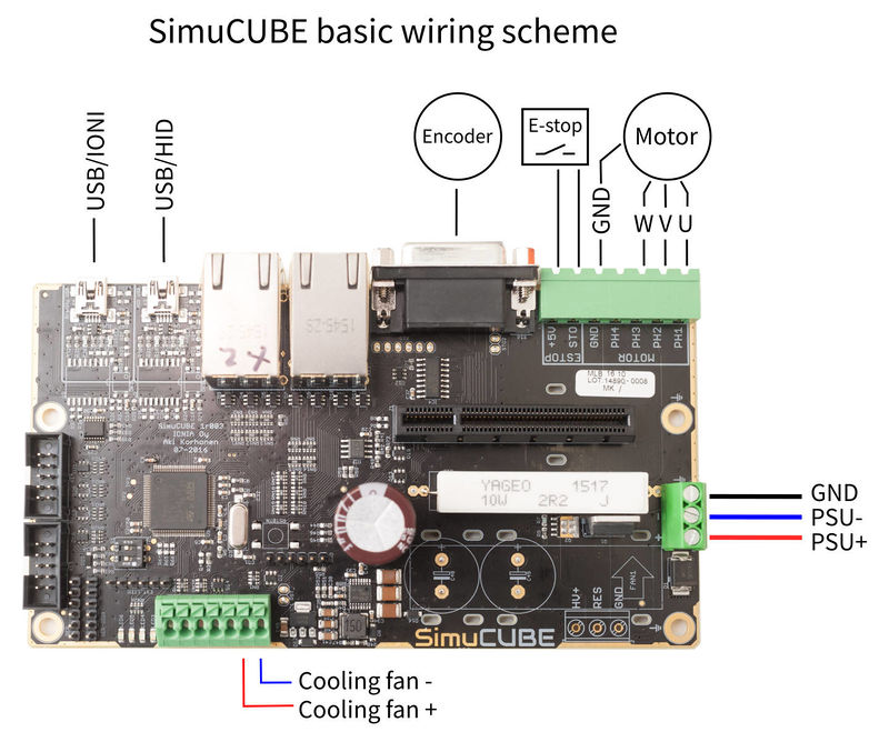
Basic wiring scheme
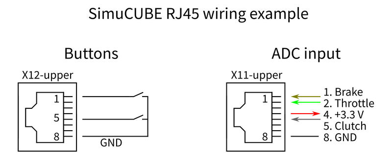
RJ45 connector wiring examples

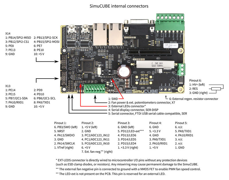
Internal connector pinouts
| EXT-LEDS connector is directly wired to microcontroller I/O pins without any protection devices (such as ESD clamp diodes, or resistors). Any miswiring may cause permanent damage to the drive. |
| Damage caused through EXT-LEDS connector is not covered by the warranty. |


