Difference between revisions of "SimuCUBE pinouts and wiring"
| [checked revision] | [checked revision] |
(→Internal connector pinouts) |
(Fix X11-lower Button 15 (PC15) NC by firmware) |
||
| (6 intermediate revisions by 2 users not shown) | |||
| Line 78: | Line 78: | ||
===X12-upper=== | ===X12-upper=== | ||
Pin 1 is the right-most. These are active-low with an internal 3.3 kOhm pull-up resistor.<br> | Pin 1 is the right-most. These are active-low with an internal 3.3 kOhm pull-up resistor.<br> | ||
| − | Use with a RJ45 (8P8C) modular connector. Can be used with straight unshielded or shielded CAT3/5/5e cables (<b>don't</b> use crossover cables!) | + | Use with a RJ45 (8P8C) modular connector. Can be used with straight unshielded or shielded CAT3/5/5e cables (<b>don't</b> use crossover cables!)<br> |
| + | Configuration of input modes is done in the X12 input configuration dialog in SimuCUBE firmware 0.11.0 and later. If Buttons is configured, then optionally pin 7 can be a shift button, which will affect both X12 inputs pins so that buttons 1-16 will become 17-32. | ||
{| class="wikitable" | {| class="wikitable" | ||
|- | |- | ||
| − | ! Pin number !! Signal name !! STM32F407 pin !! Usage | + | ! Pin number !! Signal name !! STM32F407 pin !! Usage if Button !! Usage if Encoder |
|- | |- | ||
| − | | 1 || class="inpin" | Button 1|| PC11|| Digital input for button | + | | 1 || class="inpin" | Button 1|| PC11|| Digital input for button || Encoder button(s) (all of them) |
|- | |- | ||
| − | | 2 || class="inpin" | Button 2|| PC6|| Digital input for button | + | | 2 || class="inpin" | Button 2|| PC6|| Digital input for button || Encoder 1 A / CW |
|- | |- | ||
| − | | 3 || class="inpin" | Button 3|| PC7|| Digital input for button | + | | 3 || class="inpin" | Button 3|| PC7|| Digital input for button || Encoder 1 B / CCW |
|- | |- | ||
| − | | 4 || class="inpin" | Button 4|| PC8|| Digital input for button | + | | 4 || class="inpin" | Button 4|| PC8|| Digital input for button || Encoder 2 A / CW |
|- | |- | ||
| − | | 5 || class="inpin" | Button 5|| PC9|| Digital input for button | + | | 5 || class="inpin" | Button 5|| PC9|| Digital input for button || Encoder 2 B / CCW |
|- | |- | ||
| − | | 6 || class="inpin" | Button 6|| PE5|| Digital input for button | + | | 6 || class="inpin" | Button 6|| PE5|| Digital input for button || Encoder 3 A / CW |
|- | |- | ||
| − | | 7 || class="inpin" | Button 7|| PC10|| Digital input for button | + | | 7 || class="inpin" | Button 7|| PC10|| Digital input for button || Encoder 3 B / CCW |
|- | |- | ||
| − | | 8 || class="powpin" | GND / 0 V|| || Ground | + | | 8 || class="powpin" | GND / 0 V|| || Ground|| Ground |
|} | |} | ||
===X12-lower=== | ===X12-lower=== | ||
Pin 1 is the left-most. These are active-low with an internal 3.3 kOhm pull-up resistor.<br> | Pin 1 is the left-most. These are active-low with an internal 3.3 kOhm pull-up resistor.<br> | ||
| − | Use with a RJ45 (8P8C) modular connector. Can be used with straight unshielded or shielded CAT3/5/5e cables (<b>don't</b> use crossover cables!) | + | Use with a RJ45 (8P8C) modular connector. Can be used with straight unshielded or shielded CAT3/5/5e cables (<b>don't</b> use crossover cables!)<br> |
| + | Configuration of input modes is done in the X12 input configuration dialog in SimuCUBE firmware 0.11.0 and later. If Buttons is configured, then optionally pin 7 can be a shift button, which will affect both X12 inputs pins so that buttons 1-16 will become 17-32. | ||
{| class="wikitable" | {| class="wikitable" | ||
|- | |- | ||
| − | ! Pin number !! Signal name !! STM32F407 pin !! Usage | + | ! Pin number !! Signal name !! STM32F407 pin !! Usage if button !! Usage if Encoder |
|- | |- | ||
| − | | 1 || class="inpin" | Button 8|| PE2|| Digital input for button | + | | 1 || class="inpin" | Button 8|| PE2|| Digital input for button || Encoder button(s) (all of them) |
|- | |- | ||
| − | | 2 || class="inpin" | Button 9|| PE3|| Digital input for button | + | | 2 || class="inpin" | Button 9|| PE3|| Digital input for button || Encoder 4 A / CW |
|- | |- | ||
| − | | 3 || class="inpin" | Button 10|| PE1|| Digital input for button | + | | 3 || class="inpin" | Button 10|| PE1|| Digital input for button || Encoder 4 B / CCW |
|- | |- | ||
| − | | 4 || class="inpin" | Button 11|| PE0|| Digital input for button | + | | 4 || class="inpin" | Button 11|| PE0|| Digital input for button || Encoder 5 A / CW |
|- | |- | ||
| − | | 5 || class="inpin" | Button 12|| PC12|| Digital input for button | + | | 5 || class="inpin" | Button 12|| PC12|| Digital input for button || Encoder 5 B / CCW |
|- | |- | ||
| − | | 6 || class="inpin" | Button 13|| PC13|| Digital input for button | + | | 6 || class="inpin" | Button 13|| PC13|| Digital input for button || Encoder 6 A / CW |
|- | |- | ||
| − | | 7 || class="inpin" | Button 14|| PC14|| Digital input for button | + | | 7 || class="inpin" | Button 14|| PC14|| Digital input for button || Encoder 6 B / CCW |
|- | |- | ||
| − | | 8 || class="powpin" | GND / 0 V|| || Ground | + | | 8 || class="powpin" | GND / 0 V|| || Ground|| Ground |
|} | |} | ||
| Line 157: | Line 159: | ||
! Pin number !! Signal name !! STM32F407 pin !! Usage | ! Pin number !! Signal name !! STM32F407 pin !! Usage | ||
|- | |- | ||
| − | | 1 || class="inpin" | Button 15|| PC15|| | + | | 1 || class="inpin" | Button 15|| PC15|| No firmware support |
|- | |- | ||
| 2 || class="inpin" | ADC123_IN13|| PC3|| ADC input | | 2 || class="inpin" | ADC123_IN13|| PC3|| ADC input | ||
| Line 193: | Line 195: | ||
{{damage|EXT-LEDS connector is directly wired to microcontroller I/O pins without any protection devices (such as ESD clamp diodes, or resistors). Any miswiring may cause permanent damage to the drive.}} | {{damage|EXT-LEDS connector is directly wired to microcontroller I/O pins without any protection devices (such as ESD clamp diodes, or resistors). Any miswiring may cause permanent damage to the drive.}} | ||
{{info|Damage caused through EXT-LEDS connector is not covered by the [[Product warranty terms|warranty]].}} | {{info|Damage caused through EXT-LEDS connector is not covered by the [[Product warranty terms|warranty]].}} | ||
| − | [[File:Simucube | + | [[File:Simucube internal connectors.jpg|thumb|800px|center|SimuCUBE 1r004 internal connectors.]] |
==External resistor connection== | ==External resistor connection== | ||
Latest revision as of 07:54, 17 July 2019
External connectors[edit | edit source]
Legend[edit | edit source]
| Color |
|---|
| Supply pin |
| Input pin |
| Output pin |
X1 - Motor & E-stop connector[edit | edit source]
| Pin number | Signal name | Usage |
|---|---|---|
| 1 | U / PH1 | Motor phase 1 / Servo U |
| 2 | V / PH2 | Motor phase 2 / Servo V |
| 3 | W / PH3 | Motor phase 3 / Servo W |
| 4 | PH4 | Motor phase 4 |
| 5 | GND | Ground voltage (0 V) of the SimuCUBE, shield |
| 6 | E-Stop / STO | External stop / Safe Torque Off input pin (active high) |
| 7 | +5 V | 5 V supply voltage |
X16 - Motor position sensor connector[edit | edit source]
A, B, and C indicate the quadrature encoder differential signals.
| Pin # | Pin name | Quadrature encoder | SinCos encoder | BiSS-C encoder |
|---|---|---|---|---|
| Shell | GND | Earth / 0 V | Earth / 0 V | Earth / 0 V |
| 1 | HALL_W | Hall sensor digital input W | Hall sensor digital input W | |
| 2 | HALL_V | Hall sensor digital input V | Hall sensor digital input V | |
| 3 | HALL_U | Hall sensor digital input U | Hall sensor digital input U | |
| 4 | GND | Encoder supply ground / 0 V | Encoder supply ground / 0 V | Encoder supply ground / 0 V |
| 5 | B- | Encoder differential input B- | SinCos input B- | |
| 6 | B+ | Encoder differential input B+ | SinCos input B+ | |
| 7 | A- | Encoder differential input A- | SinCos input A- | |
| 8 | A+ | Encoder differential input A+ | SinCos input A+ | |
| 9 | 5V_OUT | Encoder supply +5 V output | Encoder supply +5 V output | Encoder supply +5 V output |
| 10 | GND | Encoder supply ground / 0 V | Encoder supply ground / 0 V | Encoder supply ground / 0 V |
| 11 | GPI3 | IONI GPI3 input | Clock- / MA- | |
| 12 | GPI2 | IONI GPI2 input | Clock+ / MA+ | |
| 13 | GPI1 | IONI GPI1 input | ||
| 14 | C- | Encoder differential input C- (index channel) | Encoder differential input C- (index channel) | Data- / SLO- |
| 15 | C+ | Encoder differential input C+ (index channel) | Encoder differential input C+ (index channel) | Data+ / SLO+ |
X12-upper[edit | edit source]
Pin 1 is the right-most. These are active-low with an internal 3.3 kOhm pull-up resistor.
Use with a RJ45 (8P8C) modular connector. Can be used with straight unshielded or shielded CAT3/5/5e cables (don't use crossover cables!)
Configuration of input modes is done in the X12 input configuration dialog in SimuCUBE firmware 0.11.0 and later. If Buttons is configured, then optionally pin 7 can be a shift button, which will affect both X12 inputs pins so that buttons 1-16 will become 17-32.
| Pin number | Signal name | STM32F407 pin | Usage if Button | Usage if Encoder |
|---|---|---|---|---|
| 1 | Button 1 | PC11 | Digital input for button | Encoder button(s) (all of them) |
| 2 | Button 2 | PC6 | Digital input for button | Encoder 1 A / CW |
| 3 | Button 3 | PC7 | Digital input for button | Encoder 1 B / CCW |
| 4 | Button 4 | PC8 | Digital input for button | Encoder 2 A / CW |
| 5 | Button 5 | PC9 | Digital input for button | Encoder 2 B / CCW |
| 6 | Button 6 | PE5 | Digital input for button | Encoder 3 A / CW |
| 7 | Button 7 | PC10 | Digital input for button | Encoder 3 B / CCW |
| 8 | GND / 0 V | Ground | Ground |
X12-lower[edit | edit source]
Pin 1 is the left-most. These are active-low with an internal 3.3 kOhm pull-up resistor.
Use with a RJ45 (8P8C) modular connector. Can be used with straight unshielded or shielded CAT3/5/5e cables (don't use crossover cables!)
Configuration of input modes is done in the X12 input configuration dialog in SimuCUBE firmware 0.11.0 and later. If Buttons is configured, then optionally pin 7 can be a shift button, which will affect both X12 inputs pins so that buttons 1-16 will become 17-32.
| Pin number | Signal name | STM32F407 pin | Usage if button | Usage if Encoder |
|---|---|---|---|---|
| 1 | Button 8 | PE2 | Digital input for button | Encoder button(s) (all of them) |
| 2 | Button 9 | PE3 | Digital input for button | Encoder 4 A / CW |
| 3 | Button 10 | PE1 | Digital input for button | Encoder 4 B / CCW |
| 4 | Button 11 | PE0 | Digital input for button | Encoder 5 A / CW |
| 5 | Button 12 | PC12 | Digital input for button | Encoder 5 B / CCW |
| 6 | Button 13 | PC13 | Digital input for button | Encoder 6 A / CW |
| 7 | Button 14 | PC14 | Digital input for button | Encoder 6 B / CCW |
| 8 | GND / 0 V | Ground | Ground |
X11-upper[edit | edit source]
Pin 1 is the right-most.
Use with a RJ45 (8P8C) modular connector. Can be used with straight unshielded or shielded CAT3/5/5e cables (don't use crossover cables!)
Note: These analog inputs are 3.3 V tolerant. Do not connect 5 V signals.
| Pin number | Signal name | STM32F407 pin | Usage |
|---|---|---|---|
| 1 | ADC12_IN9 | PB1 | ADC input for brake pedal |
| 2 | ADC12_IN8 | PB0 | ADC input for throttle pedal |
| 3 | ADC12_IN14 | PC5 | ADC input |
| 4 | VCC_OUT | +3.3 V supply | |
| 5 | ADC12_IN4 | PC4 | ADC input for clutch pedal |
| 6 | ADC12_IN7 | PA7 | ADC input |
| 7 | HX711_CLKOUT | PE12 | Reserved for future use |
| 8 | GND / 0 V | Ground |
X11-lower[edit | edit source]
Pin 1 is the left-most.
Use with a RJ45 (8P8C) modular connector. Can be used with straight unshielded or shielded CAT3/5/5e cables (don't use crossover cables!)
Note: These analog inputs are 3.3 V tolerant. Do not connect 5 V signals.
| Pin number | Signal name | STM32F407 pin | Usage |
|---|---|---|---|
| 1 | Button 15 | PC15 | No firmware support |
| 2 | ADC123_IN13 | PC3 | ADC input |
| 3 | ADC123_IN3 | PA3 | ADC input |
| 4 | VCC_OUT | +3.3 V supply | |
| 5 | ADC12_IN4 / DAC1 | PA4 | ADC input (/ DAC output) |
| 6 | ADC12_IN5 / DAC2 | PA5 | ADC input (/ DAC output) |
| 7 | ADC12_IN6 | PA6 | ADC input |
| 8 | GND / 0 V | Ground |
USB Connectors[edit | edit source]
| Connector | Usage | Notes |
|---|---|---|
| X3 | USB connector for the STM32F4 | |
| X4 | USB connector for the IONI |
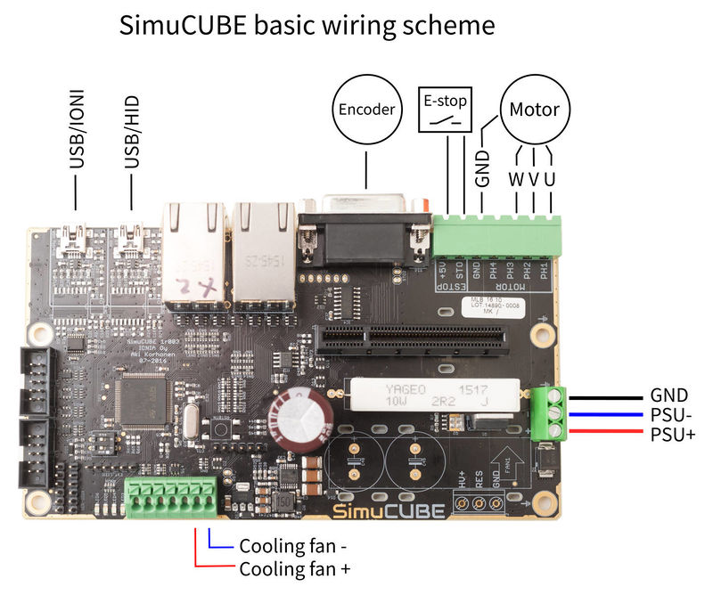
Basic wiring scheme[edit | edit source]
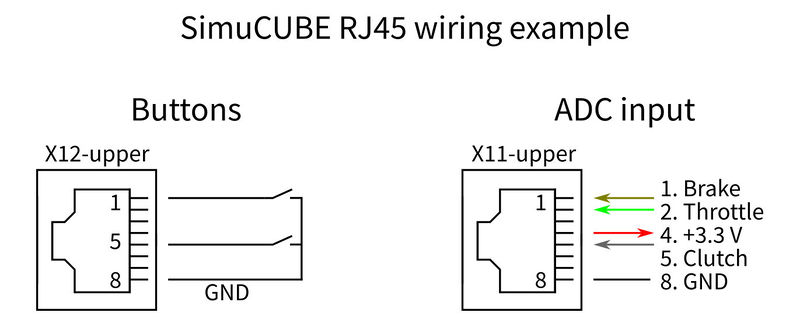
RJ45 connector wiring examples[edit | edit source]

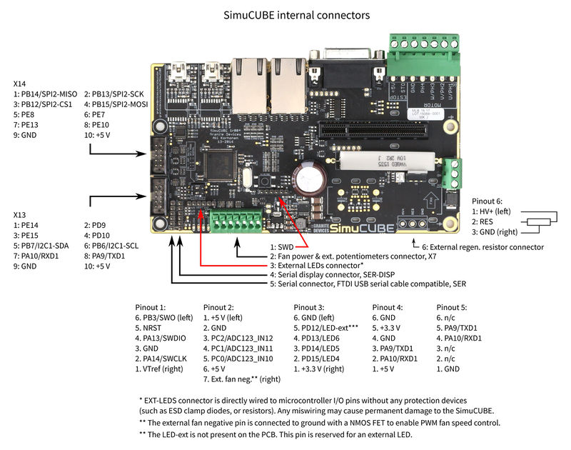
Internal connector pinouts[edit | edit source]
| EXT-LEDS connector is directly wired to microcontroller I/O pins without any protection devices (such as ESD clamp diodes, or resistors). Any miswiring may cause permanent damage to the drive. |
| Damage caused through EXT-LEDS connector is not covered by the warranty. |
External resistor connection[edit | edit source]
For SimuCUBE Hardware Revision 2 (1r005 printed on the PCB), it is possible to use an external regenerative braking resistor. Suitable external resistor should have resistance of 2.5 Ohm and rated power of at least 25 Watts. We recommend 50 Watts.
Please note, that if, for whatever reason, the internal resistor on the SimuCUBE has cracked, the steps listed SimuCUBE troubleshooting should be performed to analyze the health of the MOSFET transistor.
On SimuCUBE 1r005, the pinout of the external resistor connection has changed compared to the above image. Please refer to the markings on the SimuCUBE board.
| Internal/External resistor in use | Pins connected in the screw terminal | Default from factory |
|---|---|---|
| Internal | Resistor Input and Internal Resistor connected via a jumper block | Default |
| External | Remove jumper and connect external resistor between Resistor Input and HV BUS Output |


