Difference between revisions of "Argon user guide/Wiring"
| [checked revision] | [checked revision] |
(→Wiring overview) |
(→Wiring overview) |
||
| Line 1: | Line 1: | ||
{{ArgonManualNav}} | {{ArgonManualNav}} | ||
==Wiring overview== | ==Wiring overview== | ||
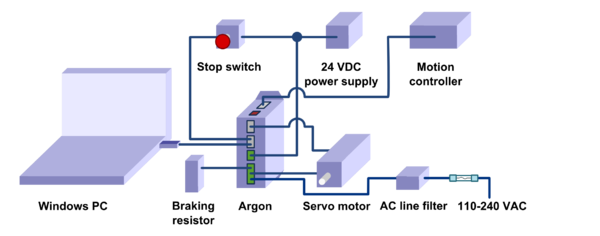
| − | [[File:Wiringoverview notitle.png| | + | [[File:Wiringoverview notitle.png|600px]] |
;The minimum wiring for a servo system (after configuration state): | ;The minimum wiring for a servo system (after configuration state): | ||
Revision as of 13:11, 1 September 2013
Wiring overview
- The minimum wiring for a servo system (after configuration state)
- Safety earthing to port J4 and preferably to the Argon case
- 24 VDC wiring to port J3
- Safe torque off and enable signals to port J2. See how.
- Motion controller wiring:
- if pulse & direction, analog, PWM or quadrature setpoint signal used, wire signals to port J5
- if setpoint delivered over SimpleMotion V2 bus, then a cable from SimpleMotion V2 compatible communication interface device to J2
- Axis limit switches wired to port J5
- Feedback device wiring to port J1
- Motor connection to port J4
- AC input power to port J4. Use an external fuse with this input.
- Optional wiring
- AC Power line filter on the wire entering J4
- Wiring of optional braking resistor to port J4
- Motor solenoid brake wiring to port J3
- Additionally following are required for drive configuration with Granity
- A cable from SimpleMotion V2 USB adapter to port J2
Ports and connectors
J1 feedback device port
J1 connector type is 15 pin female D-Sub and should be mated with 15 pin male D-Sub counterpart.
For pin-out and connection examples, see the main article J1 connector wiring.
J2.1 and J2.2 Simplemotion & E-stop ports
J2.1 and J2.2 are RJ45 type connectors and mates with standard Cat 5 & 6 Ethernet cables. Both of these ports are connected pin-to-pin parallel to allow chaining of Argon devices.
See the main article SimpleMotion V2 port.
J3 24V power and motor brake port
J3 is a 3 pole terminal block type connector used for supplying 24VDC to drive and optionally controlling motor solenoid brake.
See the main article J3 connector wiring.
J4 power & motor port
J4 is a 10 pole terminal block connector for several functions: earthing, AC power input, motor output, regenerative resistor output and HV DC link sharing.
See the main article J4 connector wiring.
J5 Inputs/Outputs
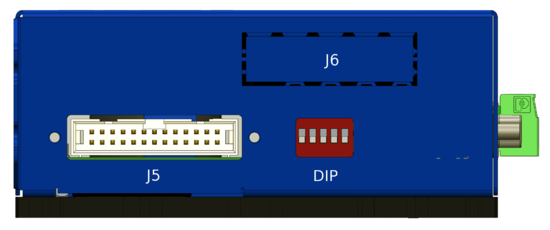
J5 Is a 26 pin IDC connector located on the side of Argon. The connector serves as general purpose I/O with setpoint signal inputs featuring: limit & home switch inputs, status indicator outputs, analog, pulse and direction, quadrature or PWM types of setpoint inputs and secondary feedback device input.
See the main article Argon I/O connector electrical interfacing for pin-out and wiring guide.
J6 Expansion slot
This slot is reserved for Argon add-on card that may be installed inside the drive.
DIP Switches
DIP switches serves as address selector when connecting the drive to SimpleMotion V2 bus or Granity.
See the main article Setting device bus address.
Mating parts
See list of Argon mating connectors and accessories
Wiring recommendations
Read general wiring recommendations articles at:
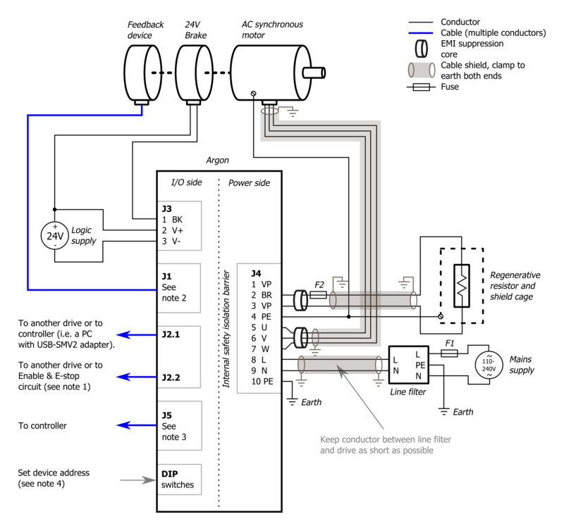
Basic wiring scheme
Before wiring, be sure to read through the main articles regarding J1-J5 ports.


