Difference between revisions of "SimuCUBE troubleshooting"
| [checked revision] | [checked revision] |
(→USB port physical issue) |
(→Over voltage fault) |
||
| Line 12: | Line 12: | ||
== Over voltage fault == | == Over voltage fault == | ||
| − | Even with features to reduce the risk, there is a chance that the regenerative resistor circuitry gets damaged. To prevent this, use the latest firmware, and double check your FOV (over voltage fault) setting in Granity. | + | Even with features to reduce the risk, there is a chance that the regenerative resistor circuitry gets damaged. To prevent this, use the latest firmware, and double check your FOV (over voltage fault) setting in Granity. This setting should be around 2 V higher than the HV Bus Voltage. E.g. 48 V HV bus voltage must be 50 V or higher. IONI servo drive needs some headroom over the FOV setting before hitting its internal hard-fault limit, so setting higher FOV than this guideline is to be avoided. |
To check if the regenerative circuitry is damaged, a multimeter (resistance meter) is needed. | To check if the regenerative circuitry is damaged, a multimeter (resistance meter) is needed. | ||
Revision as of 14:13, 27 November 2024
This page lists common pitfalls and solutions regarding SimuCUBE. Please also refer to common firmware-related troubleshooting steps described in SimuCUBE Firmware User Guide.End-Of-Life for Simucube 1
Granite Devices / Simucube announced the End-Of-Life for the Simucube 1 product in May 2022.
Software support will be active to the end of 2024 if not longer.
Hardware support has continued up to October 2024 by supplying replacement units. However since then, we have run out of replacement units and cannot sell any new replacement units.
Repair troubleshooting tips will continue to be added on to this page.
Over voltage fault
Even with features to reduce the risk, there is a chance that the regenerative resistor circuitry gets damaged. To prevent this, use the latest firmware, and double check your FOV (over voltage fault) setting in Granity. This setting should be around 2 V higher than the HV Bus Voltage. E.g. 48 V HV bus voltage must be 50 V or higher. IONI servo drive needs some headroom over the FOV setting before hitting its internal hard-fault limit, so setting higher FOV than this guideline is to be avoided.
To check if the regenerative circuitry is damaged, a multimeter (resistance meter) is needed. Please note, that some multimeters do not compensate for the test wire resistance, and this might lead to higher value when measuring the resistor.
Turn off the Simucube and disconnect power wires before attempting the measurement.
SimuCUBE 1r005
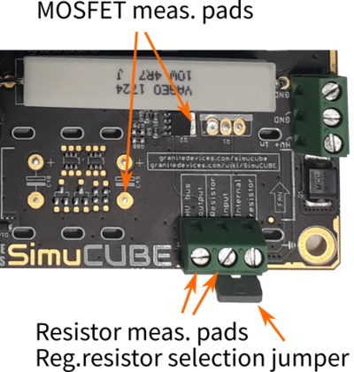
- Measure the resistance from the X2 pad HV bus output to Resistor input. The measured resistance should be close to 2.2 Ohm in single resistor SimuCUBE boards, and close to 2.35 Ohm in boards where two resistors are soldered.
- Measure the resistance from the surface mounted transistor tab to GND. Please refer to the image for test points. The measured resistance should stabilize close to 6 kOhms.
- Measuring with automatic range, the MOSFET resistance measures as described in 1r004 section.
- Measuring with 20 kOhm range, the MOSFET resistance rises slowly from < 1 kOhm to 6 kOhm.
SimuCUBE 1r004
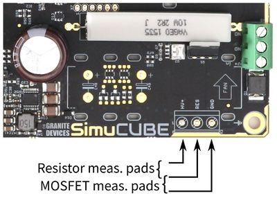
- Measure the resistance from the X2 pad HV+ to RES. The measured resistance should be close to 2.2 Ohm in single resistor SimuCUBE boards, and close to 2.35 Ohm in boards where two resistors are soldered.
- Measure the resistance from the X2 pad RES to GND. The measured resistance should be around 12..15 kOhm, changing (lowering) slowly.
Should the resistor measure more than 5 Ohm, and/or the MOSFET measures less than 10 kOhm, then double check your measurement, and if the results persist, then the respective component need to be changed.
Fixing the fault
Replace the regenerative braking resistors. Suitable resistance is around 2.5 ohms. Soldering two 4.7 ohm or 5.0 ohm resistors in parallel, like they are in the 1r005 revision, is preferred solution. Suitable part number for 5.0 ohm version is Yageo SQP10AJB-5R or similar.
Usually also the MOSFET needs to be replaced. The original part is not made anymore (EOL). Suitable replacements are PSMN014-80YLX, BUK9Y14-80E or with similar ones that have even higher voltage tolerance. Use a MOSFET that is fully open at 3.3 V gate voltage, and that it's Rdson is equal or less than 22 mOhm.
SimuCUBE won't go into DFU mode
- If device does not appear as DFU mode device when plugged in, check Windows Device Manager if there is any unknown USB devices. If yes, then try unplugging SimuCUBE USB cable and see if that device disappears. If this is the case, then it indicates that device driver is not installed properly. Try installing ST DfuSeDemo software with drivers to solve the issue. DfuSeDemo Installation Directory will contain the required drivers.
- Maybe USB device is not recognized at all? Keep Device Manager open and plug/unplug SimuCUBE while keeping eye on the Device Manager list. If you see list refresh, then it is a sign that device has entered/left the list. If nothing happens, then it might indicate hardware issue as no USB device is recognized at all.
- Download & use USBDeview to see whether STM32 BOOTLOADER device or any device missing driver is listed:
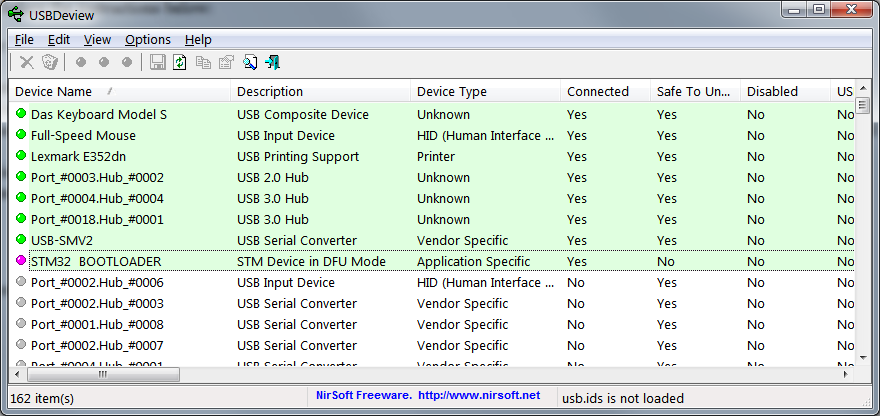
SimuCUBE unexpectedly stuck in DFU mode
It is possible, but very rare, that SimuCUBE gets stuck in DFU mode or switches to DFU mode by itself without user interaction. Please refer to separate support article: SimuCUBE stuck in DFU mode
SimuCUBE worked but does not talk from X3 USB anymore
Symptom: Simucube 1 board does not show as a game controller from the X3 USB port anymore. It may show on PC as an unrecognized USB device or "device cannot start".
Troubleshoot in DFU mode
Power off the device, move both of the small dip switches on the board to the other position. This make the STM32F407 microcontroller to boot up in its internal bootloader mode. This should present the device as an STM32 Bootloader or STM32 Device in DFU mode on PC when you next start it.
If this happens, you can use DfuSeDemo software to re-flash the Simucube bootloader and firmware to device.
Follow to next step if this didn't help.
Check the USB ESD protection diodes
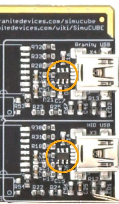
The USB ESD protection diode module can burn itself in to short circuit, that can cause this issue.
Power off the device and disconnect it from PC / USB.
Measure the resistance between the GND (top middle) and data pads (top left, and bottom left) on the protection diode. The diode module is the 6-pin component right next to the X3 USB port on the circuit board.
If the diode is shorted out, it can be removed to remove the short circuit. Caution: Hot air station must be used in melting the solder, otherwise the procedure might damage the traces on the circuit board.
If device starts to work with removed diode, a suitable replacement for the diode is ST Microelectronics USBLC6-4SC6.
If diode removal didn't help, the issue is likely in the microcontroller itself.
Microcontroller fault
The STM32F407 microcontroller can fail internally so that it appears to work just fine and even the communications with the servo drive work fine, and the motor will make the startup beep tones. However, it just won't talk via the USB X3 connector anymore. Replacing the microcontroller is possible. Caution: Hot air must be used in melting the solder when removing the component, otherwise the procedure might damage the traces on the circuit board. Since the component has high pin count, the procedure requires professional electronics reworking skills.
Suitable component is the STM32F407VE (512 kB memory) or STM32F407VG (1024 kB memory) in LQFP 100 package. Component ordering numbers are STM32F407VET6 and STM32F407VGT6.
After replacement, the microcontroller must be programmed with the Simucube bootloader and firmware again by using DfuSeDemo software.
USB port physical issue
USB port(s) can be ripped away from the PCB due to physical accident such as pulling the USB wire sideways.
Parts that can be used for a new Mini USB port are TE Connectivity AMP Connectors 1734035-2 or EDAC Inc. 690-005-299-043.
Note, that it is likely that the PCB traces are also damaged if the port is pulled with force. Care must be taken in repairing the port.
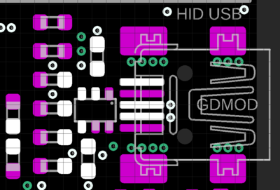
Contact Simucube support if you need schematics / layout diagram. This is likely in a case if the USB port has pulled so many traces that it is not possible to just solder a new port in.
