Difference between revisions of "Argon user guide/J4 connector wiring"
From Granite Devices Knowledge Wiki
| [checked revision] | [checked revision] |
(→J4 wiring guide) |
(→Pin-out) |
||
| Line 25: | Line 25: | ||
| 9||N || AC mains supply Neutral || colspan=2|Connect to AC supply neutral | | 9||N || AC mains supply Neutral || colspan=2|Connect to AC supply neutral | ||
|- | |- | ||
| − | | 10||PE ⏚ || Protective earth || colspan=2|Connect to supply protective earth. <span style="color:# | + | | 10||PE ⏚ || Protective earth || colspan=2|Connect to supply protective earth. <span style="color:#ee0000">This connection is always mandatory when any voltage larger than 30 VAC or 42 VDC is supplied to the device!</span>. See [[Argon user guide/Earthing]]. |
|} | |} | ||
¹ In some motors U,V,W phases are called R,S,T instead. | ¹ In some motors U,V,W phases are called R,S,T instead. | ||
| + | |||
==J4 wiring guide== | ==J4 wiring guide== | ||
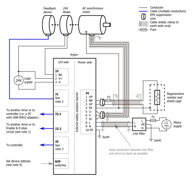
Basic wiring scheme of Argon (servo drive). Use of shielded cables is optional but highly recommended for EMI compliance and optimal reliability. For recommended accessories, EMI filters etc, see [[Argon user guide/Mating connectors and accessories|Mating connectors and accessories]]. | Basic wiring scheme of Argon (servo drive). Use of shielded cables is optional but highly recommended for EMI compliance and optimal reliability. For recommended accessories, EMI filters etc, see [[Argon user guide/Mating connectors and accessories|Mating connectors and accessories]]. | ||
Revision as of 21:56, 3 September 2013
J4 is a 10 pole terminal block connector for several functions: earthing, AC power input, motor output, regenerative resistor output and HV DC link sharing. See also the main article about Argon wiring.
| Dangerous & non-isolated mains potential voltages are present in the connector J4! Keep away from this connector and its wiring when drive has been powered recently. Carefully read the page Power supply safe discharging before operating. |
Pin-out
| Pin # | Pin name | Descrpition | AC/BLDC motor connection | Brush DC motor connection |
|---|---|---|---|---|
| 1 | VN | HV DC link negative rail | Do not connect | |
| 2 | BR | Braking resistor output | Optional braking resistor terminals. See Argon braking resistor | |
| 3 | VP | HV DC link positive rail | ||
| 4 | PE ⏚ | Protective earth | Connect to motor PE conductor and motor cable shield | |
| 5 | U | Motor phase output | Motor U phase ¹ | Motor armature+ |
| 6 | V | Motor phase output | Motor V phase ¹ | Motor armature- |
| 7 | W | Motor phase output | Motor W phase ¹ | No connection |
| 8 | L | AC mains supply Line | Connect to AC supply line | |
| 9 | N | AC mains supply Neutral | Connect to AC supply neutral | |
| 10 | PE ⏚ | Protective earth | Connect to supply protective earth. This connection is always mandatory when any voltage larger than 30 VAC or 42 VDC is supplied to the device!. See Argon user guide/Earthing. | |
¹ In some motors U,V,W phases are called R,S,T instead.
J4 wiring guide
Basic wiring scheme of Argon (servo drive). Use of shielded cables is optional but highly recommended for EMI compliance and optimal reliability. For recommended accessories, EMI filters etc, see Mating connectors and accessories.
