Difference between revisions of "Setting device bus address"
| [checked revision] | [checked revision] |
(→Ioni/Ionicube) |
|||
| (2 intermediate revisions by one other user not shown) | |||
| Line 1: | Line 1: | ||
{{ArgonManualNav}}All [[SimpleMotion V2]] compatible devices have a settable address that identifies the device on a multidrop communication bus. Each device sharing the same bus must have an unique address number to make error free communication possible. For example configuring bus address is required to establish a connection with [[Granity]] software. | {{ArgonManualNav}}All [[SimpleMotion V2]] compatible devices have a settable address that identifies the device on a multidrop communication bus. Each device sharing the same bus must have an unique address number to make error free communication possible. For example configuring bus address is required to establish a connection with [[Granity]] software. | ||
| − | + | ||
| − | + | When accessing drive through [[SimpleMotion V2]] bus, each device in the bus should be assigned to different address between 1 to 32. Device address is a sum of hardware setting and software parameter {{param|SMO}} (IONI only). The address of device is determined at the moment of logic voltage power on and will become by sum of hardware setting and SMO. | |
| + | |||
===Argon=== | ===Argon=== | ||
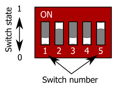
[[File:Dipswitch.png|thumb|DIP switch of Argon. In this case the DIP has value 01001.]] | [[File:Dipswitch.png|thumb|DIP switch of Argon. In this case the DIP has value 01001.]] | ||
| Line 75: | Line 76: | ||
|- | |- | ||
|} | |} | ||
| + | ===Ioni/Ionicube=== | ||
| + | When chaining multiple [[IONICUBE 1X]] motherboards (where all of them have address 1), it is necessary to utilize software parameter {{param|SMO}}. Procedure for setting unique address for each device with SMO: | ||
| + | |||
| + | #Disconnect or unpower all other devices that the ones with already unique address (i.e. have only one IONICUBE connected to SM bus, or powered on) | ||
| + | #Connect to drive with Granity | ||
| + | #Adjust SMO parameter value so that device will receive a desired bus address. I.e. if using IONICUBE 1X, set SMO values 0, 1, 2, 3 to the different drives (drive addresses will become 1, 2, 3, 4). Or when IONICUBE (4 axis) is being used, set SMO values of drives on the first board 0, second board 4, third 8 etc (drive addresses will become 1 - 12). | ||
| + | #Save settings, disconnect and repeat the procedure for all drives. | ||
| + | |||
| + | Same goes for chaining multiple [[IONICUBE]] 4 axis boards. However as base addresses of the drives on 4 axis boards are 1, 2, 3 and 4, one needs to increment SMO parameter by 4 on each chained IONICUBE. I.e. all the drives on first board should have SMO=0, the second SMO=4 and the third SMO=8 etc. | ||
| + | {{info|For instructions of setting address of IONI in custom motherboard designs, see [[IONI connector pinout]].}} | ||
==Bus termination== | ==Bus termination== | ||
| Line 94: | Line 105: | ||
*If bus stub is too long | *If bus stub is too long | ||
| − | [[ | + | {{next|[[Argon user guide/Wiring]]}} |
| + | |||
| + | [[Category:Argon_user_guide]] | ||
| + | [[Category:IONI_user_guide]] | ||
| + | [[Category:IONICUBE]] | ||
Latest revision as of 09:23, 1 September 2017
All SimpleMotion V2 compatible devices have a settable address that identifies the device on a multidrop communication bus. Each device sharing the same bus must have an unique address number to make error free communication possible. For example configuring bus address is required to establish a connection with Granity software.When accessing drive through SimpleMotion V2 bus, each device in the bus should be assigned to different address between 1 to 32. Device address is a sum of hardware setting and software parameter SimpleMotion bus address offsetSMO (IONI only). The address of device is determined at the moment of logic voltage power on and will become by sum of hardware setting and SMO.
Argon[edit | edit source]
Argon (servo drive) has a 5 channel DIP switch that sets the address. The table below lists all possible settings of DIP switch settings. Switches 1-4 set the address and the switch number 5 sets termination on or off.
| Address | Bus termination | DIP switch setting (switches from 1 to 5) |
|---|---|---|
| 255 (firmware upgrade mode) | Off | 00000 |
| 255 (firmware upgrade mode) | On | 00001 |
| 1 | Off | 00010 |
| 1 | On | 00011 |
| 2 | Off | 00100 |
| 2 | On | 00101 |
| 3 | Off | 00110 |
| 3 | On | 00111 |
| 4 | Off | 01000 |
| 4 | On | 01001 |
| 5 | Off | 01010 |
| 5 | On | 01011 |
| 6 | Off | 01100 |
| 6 | On | 01101 |
| 7 | Off | 01110 |
| 7 | On | 01111 |
| 8 | Off | 10000 |
| 8 | On | 10001 |
| 9 | Off | 10010 |
| 9 | On | 10011 |
| 10 | Off | 10100 |
| 10 | On | 10101 |
| 11 | Off | 10110 |
| 11 | On | 10111 |
| 12 | Off | 11000 |
| 12 | On | 11001 |
| 13 | Off | 11010 |
| 13 | On | 11011 |
| 14 | Off | 11100 |
| 14 | On | 11101 |
| 15 | Off | 11110 |
| 15 | On | 11111 |
Ioni/Ionicube[edit | edit source]
When chaining multiple IONICUBE 1X motherboards (where all of them have address 1), it is necessary to utilize software parameter SimpleMotion bus address offsetSMO. Procedure for setting unique address for each device with SMO:
- Disconnect or unpower all other devices that the ones with already unique address (i.e. have only one IONICUBE connected to SM bus, or powered on)
- Connect to drive with Granity
- Adjust SMO parameter value so that device will receive a desired bus address. I.e. if using IONICUBE 1X, set SMO values 0, 1, 2, 3 to the different drives (drive addresses will become 1, 2, 3, 4). Or when IONICUBE (4 axis) is being used, set SMO values of drives on the first board 0, second board 4, third 8 etc (drive addresses will become 1 - 12).
- Save settings, disconnect and repeat the procedure for all drives.
Same goes for chaining multiple IONICUBE 4 axis boards. However as base addresses of the drives on 4 axis boards are 1, 2, 3 and 4, one needs to increment SMO parameter by 4 on each chained IONICUBE. I.e. all the drives on first board should have SMO=0, the second SMO=4 and the third SMO=8 etc.
| For instructions of setting address of IONI in custom motherboard designs, see IONI connector pinout. |
Bus termination[edit | edit source]
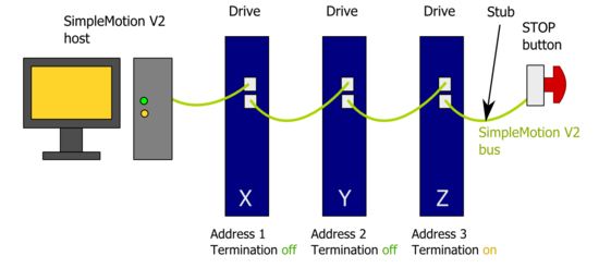
SimpleMotion V2 bus must be terminated for reliable communication. This means that last device of the bus must have termination DIP switch set to On position.Bus may be also alternatively terminated with external 100 ohm resistor connected between RS485_A and RS485_B wires at the end of bus cable chain (see SimpleMotion V2 port). If DIP switch termination is used, then drive internal 100 ohm resistor is connected across the A and B wires.
Stub[edit | edit source]
If an E-stop button is connected with RJ45 cable after the last device, a bus stub is formed. Stub must not be longer than 30 cm or 1 foot to ensure reliable bus operation.
Methods to eliminate the stub on SimpleMotion V2 port cable E-stop cable if longer than 30cm E-stop cable is needed:
- Cut the RS485_A and RS485_B wires from the cable near connector, this ends the RS485 bus next to connector and minimizes stub
- Alternatively, connect termination resistor at end of RS485_A and RS485_B wires and set DIP switch termination off
Troubleshooting[edit | edit source]
Following errors may cause unreliable connection:
- If two or more devices have same address on a single bus
- If termination is missing or is present multiple times
- If bus stub is too long
| Read next |

