IONI parameterization
This page collect most of the IONI & IONICUBE user guide articles as a single page.
Introduction to IONI
| IONI | |
|---|---|
 | |
| Device type | Servo & stepping motor drive |
| Model number | IONI-11K000, IONI-11K200 |
| Supported motors | AC, DC, BLDC, Linear, Stepper |
| Control modes | Position, Velocity, Torque |
| Status | Active production, started 2015 |
| Electrical | |
| DC supply voltage | 5 - 54 VDC (except 5 - 58 VDC in IONI Pro HC) |
| Output current range | 0.1 - 15A IONI, 0.1 - 18A IONI Pro, 0.1 - 25A IONI Pro HC |
| Setpoint signals | Pulse and direction, PWM, Analog, SimpleMotion V2 |
| Feedback devices | Quadrature encoder, SinCos encoder |
| General | |
| Configuration tool | Granity |
| Web site | Granite Devices IONI |
| Compliance | CE (EMC & LVD directives) |
| 3D model | |

IONI is a digital motor drive designed for driving AC/BLDC and DC servo motors and steppers. IONI allows controlling motors in all three operating modes: position control, velocity control and torque control (torque mode only with servo motors). Applications of such control methods include
- Position control, such as CNC, robotics and 3D printing
- Velocity control, such as spindles or feeders
- Force / torque control, such as racing simulator wheel

Commands to IONI drive can be delivered in many formats and from many sources, such as PC, PLC, microcontroller (i.e. Arduino, MBED and OEM boards) or embedded computers like Raspberry Pi. IONI understands several forms of setpoint commands:
- Step & direction digital signals (typical stepper drive interface, good for position control)
- Analog +/-10V signal (good for speed or torque control)
- PWM signal (good for speed or torque control)
- RS485 serial bus (talks SimpleMotion V2 bus protocol, open source library available)
Supported motors
As motor is not included, make sure that you have, or obtain a motor that is compatible with IONI. Learn more about motor types.
Servo motor requirements
- Permanent magnet brush-DC, AC, brushless or linear motor
- Motor voltage rating 12-60 VDC (IONI supply voltage is 5 - 52 VDC)
- Motor current rating 0.1 - 25A (choose drive model accordingly, IONI Pro HC, maximum output is 25A, IONI Pro 18A, and IONI 15A)
- Servo motor must be equipped with an supported feedback device (position sensor / encoder).
See Motor compatibility guide for more details.
Stepping motor requirements
- Two-phase stepping motor with 0.5 - 15A current rating, no feedback device needed. Can be used in position and velocity control mode. Torque mode not possible. Stepper voltage rating is irrelevant, but generally lower voltage & higher current stepper is better.
Unsuitable/non-optimum motors
- Any non-permanent magnet motors: induction AC motor or DC motor with field coil - will not work
- Cheapest grade DC motor, such as one extracted from power drill - might not give satisfying performance
- Motor with very high voltage, such as 200 VAC AC servo motor - it will work if it has incremental encoder feedback, but maximum rotation speed is limited due to drive voltage. Consider Argon servo drive for motors above 100 volts rating.
Features
State of the Art
- High dynamic range torque control
- Wide range motor support, from DC, BLDC, AC and Linear, from 5 W to 500 W
- High functional density and cost efficiency
- 3-level PWM output with reduced motor heating
- Automatically measures motor inductance and resistance for easy setup
- Anticogging / torque ripple compensation
Control
- Input setpoint signals including pulse and direction, quadrature, analog and PWM
- Multidrop & multiaxis capable real-time SimpleMotion V2 field bus for setup & control
- Internal axis homing function with sensorless hard-stop operating mode
Protections & Ruggedness
- Safe torque off
- Prevent machine damage via I²t (motor temperature modeling), blocked motion and tracking error detection
- Industry leading ruggedness: over current, short circuit, over voltage, under voltage and over temperature protections, data/communication error detection
- Warranty 24 months
- Charge pump enable input for safety
Applications
- Industrial servo & stepping motor control
- Robotics
- Industry 4.0 systems
- Testing equipment
- CNC
- Haptics
- Racing & flight simulators
- Pick'n'place machines
- Defense systems
Functionality and specifications
See main article IONI specifications.
Documentation & user guides
See the main article IONI & IONICUBE user guide.
Availability
Shipping worldwide at Granite Devices web shop.
Set-up overwies & first connection
This is the official and latest setup guide of IONI Servo Drive and IONICUBE motherboards. Read it through before installing or operating IONI series devices.| NOTE: This guide attempts to be as complete and precise as humanly possible, however it can never be perfect. Writers of this guide are not responsible if possible damages or losses caused by mistakes or lacks of this guide. |
| IMPORTANT: IONI drive should be installed and operated only by qualified electricians. Dangerous voltages and mechanics may be involved and possibility of severe injury or even death is possible in case of installation or usage errors. |

Setup process overview
Read trough the guide by following the outline on the top right side of the page and follow the hyper links to subtopics provided in the articles.

Read the page List of things needed for details.

Connect drive to PC with SimpleMotion V2 USB adapter and Granity to test connection, upgrade firmware if necessary and to learn Granity. If you're already familiar with all this, you may skip this step. Read the article Making the first Granity connection.

Carefully do the full wiring of the servo system. Consult an qualified electrician if necessary as dangerous voltages will be present. Before powering up, triple check everything by using multimeter to find short circuits. Read the main article Wiring.

Power-up the system and connect again with Granity. Now set-up the motor to work as intended. See the main article Drive parameterization. If you already have a working configuration to your motor model, you may just load the settings file to the drive.

After motor and drive are fully functional, connect motor to the mechanical load and find the optimum velocity or position control gains. Read the main article Servo motor tuning guide.
Troubleshooting
In case of troubles, refer to the articles in general troubleshooting category and IONI troubleshooting category.
| Read next |
List of items needed
- The list of necessary things to build a working servo system with IONI
- IONI drive and a compatible motherboard such as IONICUBE, IONICUBE 1X or a custom board
- SimpleMotion V2 USB adapter
- 1 or more RJ45 Ethernet cables (see details & examples)
- Regulated 24 VDC power supply, output capability at least 0.5A per motherboard
- Regulated or non-regulated 5-52 VDC power supply for motor power. Output capability depends on motor power draw. If unsure, then a good start is a power supply between 150 to 600 Watts for a multiaxis motherboard. As a reference, a typical 3 axis Nema 23 stepping motor system can be fed with a 150-200 W 48 V power supply. See:
- A IONI compatible motor
- Shielded power conductors as motor power cord. Non-shielded will also work but increase EMI and may be source of communication errors.
- Ferrite core EMI filters
- Motion controller. This may be also a software on a computer.
- Windows PC
- Optional but highly recommended items
- Emergency stop button (normally closed NC type) or equivalent
- Needed for high current motors (>5A average)
- A cooling fan
- Tools needed
- Screwdrivers
- Wire cutter
- Skills needed
- Qualified electrician skills
- Basic knowledge of servo systems
| Read next |
Making the first Granity connection
Follow the instructions to make the first Granity connection to IONI drive.Preparations
- Download and install the Granity software. Latest version can be downloaded from the link: Granity software for windows (approx 18 MB)
- Make a wiring similar to the image below
- With IONICUBE 4X revision 008 and lower, make sure that in the pinheader JP10 only position 1 has a jumper as depicted.
- With IONICUBE 4X revision 009 and higher, make sure that the switch S1 position 1 is ON and position 4 (DFU mode) is OFF.
- If you use a USB cable to connect (r. 009 and higher), turn also S1 position 2 and 3 ON.
- Connect IONICUBE to a PC
- with SimpleMotion V2 USB adapter and a straight Ethernet cable to connector X1, or
- with an USB cable without any adapters.
- Power up the 24 VDC power. Leds at the back of the IONI drive should start blinking (more about blinking sequences).
- Launch Granity software and:
- Go to Connect tab
- Ensure that "SimpleMotion V2 Adapter" is selected from dropdown menu called Communication interface device. (note 1)
- Click Connect to drive
- Once list of connected drives pop up, select the one you connected and click Open
Now if everything has gone well, you should see information about the drive model and serial number on the "Connect tab". Connection has been successfully tested and drive may be disconnected to proceed with next setup step.
Note 1) If multiple choices are named as "SimpleMotion V2 Adapter", then try each of them to find the correct one. Also if no adapters are found, try launching Granity software again as the list of adapter choices are updated only at program start-up.
IONICUBE Revision 1-8 (with jumpers)

Minimum connection for Granity
IONICUBE Revision 9 and later (with DIP switch)

SM Bus termination switch position for IONICUBE revision 009 and higher. For typical single IONICUBE wiring, set switches 1-3 to ON position and 4th OFF position.
More information about the termination and biasing of the RS485 serial bus here: Wikipedia:RS-485.
| Read next |
Wiring overwiew
IONICUBE connectors
- X1
- Dual port RJ45 connector with SimpleMotion V2 interface. For pinout, seeSimpleMotion V2 port.
- X2
- 6 pin wire terminal for logic voltage supply, Safe torque off input, analog output and relay driver outputs.
- X3
- Two pin wire terminal for HV DC bus supply.
- X4
- Main control and setpoint signal port consisting Enable input signal, Fault output signal, pulse and direction/quadrature/PWM setpoint inputs and digital outputs for home switch status. X4 is directly wired to conform most common parallel port style pulse & direction CNC controllers.
- X5
- Second control and setpoint signal port. This port consists analog setpoint signal inputs and additional digital I/O.
- X6
- These are the feedback device connector for X (lower) and Y (upper) axis motors
- X7
- These are the power and holding brake output connector for X (lower) and Y (upper) axis motors
- X8
- These are the feedback device connector for Z (lower) and A (upper) axis motors
- X9
- These are the power and holding brake output connector for Z (lower) and A (upper) axis motors
- X10
- A connector for an optional external regenerative resistor. IONICUBE has on-board regenerative resistor that is sufficient for most installations.
- IONI_X, IONI_Y, IONI_Z, IONI_A
- Card-edge connectors for IONI drives
| Before inserting or removing IONI drives from IONICUBE, remove all power from it and discharge it's capacitors. To discharge remaining energy (~voltage) from capacitors, short circuit GND to HV+ by a conductor and measure that there is no DC voltage left between GND and HV+ terminals. Even few volts left to HV DC bus is known to cause permanent damage to IONICUBE when drives are plugged. |
Front side connectors
Front side connectors consist X6, X7, X8 and X9. These connectors are the interface towards motors (motor power and feedback devices).

Connector layout and naming. View from top of the board.

IONICUBE revision 3 PCB layout. USB connector X11 and Switch S1 to replace the jumper header.

Power and feedback ports of X, Y, Z and A axis. View from plug side of the board.

Names of power and feedback ports. I.e. X9A means upper floor connector of X9 and X9B the lower floor of X9. View from plug side of the board.
Legend
| Color |
|---|
| Supply pin |
| Input pin |
| Output pin |
X7 and X9 pinout
These are the power output and holding brake output connector for motors
| Pin number | Signal name | AC/BLDC motor | Brush DC motor | Stepping motor |
|---|---|---|---|---|
| 1 | GND | Ground for cable shield and an optional motor holding brake coil | ||
| 2 | PHASE1 | U (some motors R) | Armature + | Coil A.1 |
| 3 | PHASE2 | V (some motors S) | Armature - | Coil A.2 |
| 4 | PHASE3 | W (some motors T) | Armature - | Coil B.1 |
| 5 | PHASE4 | Not connected | Armature + | Coil B.2 |
| 6 | BRAKE | Optional 24V motor holding brake coil | ||
Motor & brake wiring schematics
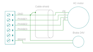
Wiring of three phase AC servo motor. Brake is optional.
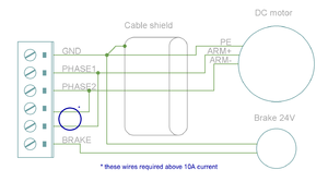
Wiring of Brush-DC servo motor. Brake is optional.
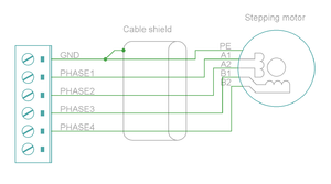
Wiring of two phase stepping motor. Brake can be fitted like in the other examples. Also 6 and 8 wire motors can be wired (the two drive coils connect always to the same PHASE outputs).


| An easy way to verify correctness of two phase stepper connection: unplug the 6 pin connector and then measure resistance between phases 1-2 and 3-4. Multimeter should show the same resistance for both cases (typically 0.1 - 5 ohms). Also when measuring between phases 1-3, 1-4, 2-3 and 2-4, the multimeter should indicate open circuit. |
X6 and X8 pinout
X6 and X8 are the feedback device connectors of motors
| Pin # | Pin name | Electrical type (in most feedback device modes) | Quadrature encoder | SinCos encoder | BiSS-C encoder | SSI encoder | AMS SSI encoder |
|---|---|---|---|---|---|---|---|
| Shell | GND | Earth/case | |||||
| 1 | HALL_W | Hall sensor digital input, phase W | - | - | - | ||
| 2 | HALL_V | Hall sensor digital input, phase V | - | - | - | ||
| 3 | HALL_U | Hall sensor digital input, phase U | - | - | - | ||
| 4 | GND | Encoder supply ground | |||||
| 5 | B- | Differential input B- | Channel B- | SinCos input B- | - | - | - |
| 6 | B+ | Differential input B+ | Channel B+ | SinCos input B+ | - | - | - |
| 7 | A- | Differential input A- | Channel A- | SinCos input A- | - | - | - |
| 8 | A+ | Differential input A+ | Channel A+ | SinCos input A+ | - | - | - |
| 9 | 5V_OUT | Encoder supply 5V output | |||||
| 10 | GND | Encoder supply ground | |||||
| 11 | GPI3 | Axis negative direction end limit switch (optional). Normally closed (NC) switch is highly recommended for safety reasons. Connect it between this pin and GND pin. Normally open (NO) switch can be used, and the switch polarity can be changed with Limit switch polarityLSP. |
Clock/MA- | Clock- | CLK | ||
| 12 | GPI2 | Axis positive direction end limit switch (optional).Normally closed (NC) switch is highly recommended for safety reasons. Connect it between this pin and GND pin. Normally open (NO) switch can be used, and the switch polarity can be changed with Limit switch polarityLSP. |
Clock/MA+ | Clock+ | CSn | ||
| 13 | GPI1 | Axis home switch switch (optional). Normally closed (NC) switch is highly recommended for safety reasons. Connect it between this pin and GND pin. Normally open (NO) switch can be used, and the switch polarity can be changed with Home switch or hard stop search direction (Home switch polarity)HMS. |
DO | ||||
| 14 | C- | Differential input C- | Index channel Z- | Index channel Z+ | Data/SLO- | Data- | - |
| 15 | C+ | Differential input C+ | Index channel Z+ | Index channel Z+ | Data/SLO+ | Data+ | - |
| Pin layout | Female D-sub 15 connector as it appears from outside of drive. Note: counterpart (male) connector has mirrored pin layout if viewed from pin side, and same layout if viewed from soldering side.
| ||||||

| Especially with long encoder cables, it might be necessary to add encoder line termination resistors, see Terminating differential encoder lines. |
Examples of feedback device and switch wiring
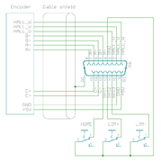
Fully wired port with differential incremental encoder, hall sensors and switches
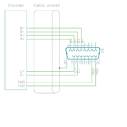
Wiring of differential incremental encoder
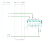
Minimal wiring of incremental encoder (single ended, no index channel)
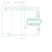
Wiring of Hall sensors only (only torque mode possible)
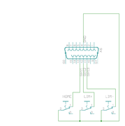
Illustration of wiring limit and home switches. In addition to this, encoder and/or halls are needed.


| In case of single-ended encoder, connect encoder's A, B, Z only to drive's A+, B+ and C+ and leave drive's A-, B- and C- unconnected. |
| With differential Hall sensor (which provides U+, U-, V+, V-, W+ and W-, connect only sensor's U+, V+ and W+ to drive's HALL_U/V/W. |
| Never connect sensor negative outputs (A-/B-/C-/U-/V-/W-) to GND. Connect them to drive's A-/B-/C- or leave unconnected. |
| Feedback devices with differential signaling may use varying naming schemes of signal pairs. For example differential signal X (which contains two electrical wires) may be denoted as: X+ and X-, or X and \X or X and X. In this Wiki we mark them X+ and X-. Some Fanuc encoders have quadrature signals named as PCA, /PCA, PCB, /PCB, PCZ and /PCZ which are equivalent to A, B and Z signal pairs. |
Back side connectors

A closeup of X2, X3, X4 and X5
| Never connect an Ethernet to X1. While it uses similar connector and cabling, it is electrically incompatible with Ethernet. Devices may be permanently damaged by mixing Ethernet and SimpleMotion V2. |
| Do now wire SimpleMotion V2 ports with crossover RJ45 cables (see details). Always use straight/non-crossover patch cables. If unsure about what is the type of your RJ45 cable, don't use it. |
X2 pinout
X2 is 6 pin wire terminal for logic voltage supply, Safe torque off input, analog output and relay driver outputs.
| Pin number | Signal name | Usage |
|---|---|---|
| 1 | GND | Ground |
| 2 | 24V | 24V logic supply |
| 3 | STO | Safe torque off input (this pin also available in X1, as defined in SimpleMotion V2 port |
| 4 | VFD | 0-12V analog output where voltage level is proportional to PWM duty cycle on pin PWM on X4. PWM frequency must be between 100 and 10000 Hz. |
| 5 | RL1 | Relay coil driver output 1. When RLIN1 on X4 is logic high, RL1 is pulled to GND by an open collector circuit. When RLIN1 is low, RL1 is floating (max 24V). When connecting a relay that has 24VDC coil between RL1 and supplied 24V, no external free-wheeling diode is needed. Output current rating is max 500 mA. |
| 6 | RL2 | Relay coil driver output 2. When RLIN2 on X4 is logic high, RL2 is pulled to GND by an open collector circuit. When RLIN1 is low, RL2 is floating (max 24V). When connecting a relay that has 24VDC coil between RL2 and supplied 24V, no external free-wheeling diode is needed. Output current rating is max 500 mA. |
X3 pinout
X3 is two pin wire terminal for HV DC bus supply.
| Pin number | Signal name | Usage |
|---|---|---|
| 1 | GND | Ground |
| 2 | HV+ | Motor power supply, HV DC bus (see IONI drive voltage range spec) |
See also:
| If using switching power supply (SMPS) as motor power supply, external rectifier diodes are needed to protect the power supplies. See See IONI power supply schemes. |
X4 pinout
X4 is main control and setpoint signal port consisting Enable input signal, Fault output signal, pulse and direction/quadrature/PWM setpoint inputs and digital outputs for home switch status. X4 is directly wired to conform most common parallel port style pulse & direction CNC controllers.
| Pin number in header | Pin number in D25 cable | Signal name | Typical usage | Pin number in header | Pin number in D25 cable | Signal name | Typical usage | |
|---|---|---|---|---|---|---|---|---|
| 1 | 1 | ENABLE | Enable all axis (with or without chargepump) | 2 | 14 | PWM | PWM input for VFD analog output | |
| 3 | 2 | HSIN1_X | Pulse/step input X | 4 | 15 | GPO4_A | Limit switch output A | |
| 5 | 3 | HSIN2_X | Direction input X | 6 | 16 | RLIN1 | Controls RL1 state | |
| 7 | 4 | HSIN1_Y | Pulse/step input Y | 8 | 17 | RLIN2 | Controls RL2 state | |
| 9 | 5 | HSIN2_Y | Direction input Y | 10 | 18 | GND | Ground | |
| 11 | 6 | HSIN1_Z | Pulse/step input Z | 12 | 19 | GND | ||
| 13 | 7 | HSIN2_Z | Direction input Z | 14 | 20 | GND | ||
| 15 | 8 | HSIN1_A | Pulse/step input A | 16 | 21 | GND | ||
| 17 | 9 | HSIN2_A | Direction input A | 18 | 22 | GND | ||
| 19 | 10 | STOP_OUT | Fault on any axis or E-stop (active low). Note: this is IONI's GPO3 signals connected in parallel between all axis / wired-or configuration. | 20 | 23 | GND | ||
| 21 | 11 | GPO4_X | Limit switch output X | 22 | 24 | GND | ||
| 23 | 12 | GPO4_Y | Limit switch output Y | 24 | 25 | GND | ||
| 25 | 13 | GPO4_Z | Limit switch output Z | 26 | N/A | Not connected | ||
| Pin layout | 
| |||||||
| Connect only to 3.3V or 5V logic circuits go any GPI, GPO and HSIN pins. Most of X4 & X5 pins are directly routed to IONI drive pins and IONI electrical ratings apply. |
Alternative setpoint signals
Setpoint mode is selected by software with parameter Setpoint inputCRI and behavior is affected by parameters Setpoint smoothingCIS, Setpoint multiplierMUL, Setpoint dividerDIV, Setpoint offset nullingCAO and Enable direction inputCED.
| Drive listens setpoint commands also always through SimpleMotion V2 interface regardess of Setpoint inputCRI paramter setting. |
| Signal name | Function | Used for | Remarks |
|---|---|---|---|
| HSIN1 | High speed digital input 1 | Depending on setpoint mode, can be either:
| |
| HSIN2 | High speed digital input 2 | Depending on setpoint mode, can be either:
| |
| ANAIN- | Differential analog negative input | Used for analog setpoint mode | Setpoint voltage is the voltage difference between ANAIN+ and ANAIN- |
| ANAIN+ | Differential analog positive input | Used for analog setpoint mode |
X5 pinout
X5 is a second control and setpoint signal port in addition to X4. This port consists analog setpoint signal inputs and additional digital I/O.
| Pin number in header | Pin number in D25 cable | Signal name | Typical usage | Pin number in header | Pin number in D25 cable | Signal name | Typical usage | |
|---|---|---|---|---|---|---|---|---|
| 1 | 1 | GND | 2 | 14 | +5V_OUT | 5V supply from IONICUBE ^2 | ||
| 3 | 2 | ANAIN-_X | +/-10V analog input X | 4 | 15 | ANAIN+_X | +/-10V analog input X | |
| 5 | 3 | ANAIN-_Y | +/-10V analog input Y | 6 | 16 | ANAIN+_Y | +/-10V analog input Y | |
| 7 | 4 | ANAIN-_Z | +/-10V analog input Z | 8 | 17 | ANAIN+_Z | +/-10V analog input Z | |
| 9 | 5 | ANAIN-_A | +/-10V analog input A | 10 | 18 | ANAIN+_A | +/-10V analog input A | |
| 11 | 6 | GPO1_X | For pin function, refer to IONI connector pinout | 12 | 19 | GPI4_X | For pin function, refer to IONI connector pinout | |
| 13 | 7 | GPO1_Y | 14 | 20 | GPI4_Y | |||
| 15 | 8 | GPO1_Z | 16 | 21 | GPI4_Z | |||
| 17 | 9 | GPO1_A | 18 | 22 | GPI4_A | |||
| 19 | 10 | GPO5_X | 20 | 23 | GPI5_X | |||
| 21 | 11 | GPO5_Y | 22 | 24 | GPI5_Y | |||
| 23 | 12 | GPO5_Z | 24 | 25 | GPI5_Z | |||
| 25 | 13 | GPO5_A | 26 | N/A | GPI5_A | |||
| Pin layout |
| |||||||
Application example
Follwing image shows typical installation schemes for pulse/direction controlled systems, typically found in PC CNC applications.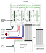
A typical connection with parallel port style CNC controller such as Mach3/Mach4/LinuxCNC. A 26 pin ribbon cable may be directly connected to PC parallel port or to equivalent pinout step/dir generator such as SmoothStepper.

| Read next |
Mating connectors and accessories
Warning: Display title "IONI Mating connectors and accessories for IONI & IONICUBE" overrides earlier display title "IONI IONI & IONICUBE wiring (4 axis IONICUBE)".
This page lists examples of available mating connectors, accessories and spare parts for IONI drive together with IONICUBE four axis motherboard. Most parts or equivalents are available from large number of distributors. You may use http://www.findchips.com/ to search the same or similar parts from alternative distributors.Recommended shopping list
- Connectors and backshells for X6/X8 unless using a motor with pre-made encoder cables (like Granite Devices servo motors)
- X1 cable (RJ45 cable)
- X4/X5 connectors and flat cable
- A flat cable to D-Sub 25 connector if direct connection to parallel port based PC CNC software is desired
- EMI filters
- 24 VDC logic power supply
- HV DC bus power supply
See the list of example parts below.
Connectors
X6 & X8 connector
| Description | Manufacturer | Part number | Distributors and order codes |
|---|---|---|---|
| PLUG, D, SOLDER, 15WAY | MULTICOMP | 5501-15PA-02-F1 |
|
Accessories
| Description | Manufacturer | Part number | Distributors and order codes |
|---|---|---|---|
| D-SUB BACKSHELL, 15WAY | MH CONNECTORS | DPPK15-GREY-K |
|
X1 connector
Cable assemblies
Cable used for X1 should be shielded (S/FTP or FTP, not UTP) type.
| Description | Manufacturer | Part number | Distributors and order codes |
|---|---|---|---|
| Premium patch cable 0.5m | VIDEK | 3962-0.5 | Farnell 1525999 |
| Premium patch cable 1m | VIDEK | 3962-1 | |
| Premium patch cable 2m | VIDEK | 3962-2 | Farnell 1525753 |
| Premium patch cable 5m | VIDEK | 3962-5 | Farnell 1525755 |
| Premium patch cable 10m | VIDEK | 3962-10 | |
| Shielded patch cable 0.5m | VIDEK | 2992-0.5 | Farnell 1517504 |
| Shielded patch cable 1m | VIDEK | 2992-1 | |
| Shielded Patch cable 2m | VIDEK | 2992-2 | Farnell 1517506 |
| Shielded patch cable 5m | VIDEK | 2992-5 | Farnell 1517509 |
| Shielded patch cable 10m | VIDEK | 2992-10 | |
| Shielded patch cable 0.5m | Assman | A-MCSP-80005/B-R | Digikey A-MCSP-80005/B-R |
| Shielded patch cable 1m | Assman | A-MCSP-80005/Y-R | Digikey A-MCSP-80010/Y-R |
| Shielded patch cable 2m | Assman | A-MCSP-80020/Y-R | Digikey A-MCSP-80020/Y-R |
| Shielded patch cable 3m | Assman | A-MCSP-80050/Y-R | Digikey A-MCSP-80030/Y-R |
| Shielded patch cable 5m | Assman | A-MCSP-80050/Y-R | Digikey A-MCSP-80050/Y-R |
| Shielded patch cable 10m | Assman | A-MCSP-80050/Y-R | Digikey A-MCSP-80100/Y-R |
Accessories
| Description | Manufacturer | Part number | Distributors and order codes |
|---|---|---|---|
| RJ45 break-out board with DIN rail fixture (convert RJ45 to screw terminals). Helpful for wiring STO and Enable wires. | Camden boss | CIM/RJ45 | Farnell 2211819 |
X7 and X9 connector
These parts are included with IONICUBE 4 axis product.
| Description | Manufacturer | Part number | Distributors and order codes |
|---|---|---|---|
| 6 pole 5mm pitch terminal plug | FCI | 20020007-G061B01LF |
X4 and X5 connector

Mating connector type is 0.1" pitch 26 pin IDC ribbon cable socket, see example (pdf).
| Description | Manufacturer | Part number | Distributors and order codes |
|---|---|---|---|
| SOCKET, IDC, 2.54MM, 26WAY | AMPHENOL | T812126A100CEU |
|
| SOCKET, IDC, WITH S/RELIEF, 26WAY | MULTICOMP | MC6FD026-30P1 |
|
| FLAT CABLE 26 WAY | 3M | 3302/26 300SF | Digikey MC26M-5-ND |
Accessories
| Description | Manufacturer | Part number | Distributors and order codes |
|---|---|---|---|
| IDC terminal block, 26WAY | Camden boss | CIM/202426W-IDCS |
|
| FLAT CABLE TO D-SUB 25 CONNECTOR | Sullins | SDS103-PRW2-M25-SN00-211 | Digikey S9577-ND |
Electromagnetic interference filtering
| Description | Manufacturer | Part number | Distributors and order codes |
|---|---|---|---|
| EMI suppression core for low frequency band | Laird | LFB159079-000 | Digikey 240-2281-ND |
| EMI suppression core for medium frequency band | Laird | 28B0616-000 | Digikey 240-2306-ND |
Power supplies
Before making decision on power supplies, see:
24V low power logic supply
| Description | Manufacturer | Part number | Distributors and order codes |
|---|---|---|---|
| 24 VDC power supply | TDK-Lambda | LS35-24 | Digikey 285-1893-ND |
| 24 VDC DIN rail power supply | CUI Inc | VDRS-20-24 | Digikey 102-2152-ND |
HV DC high power motor supply
| Voltage | Power | Manufacturer | Part number | Distributors and order codes |
|---|---|---|---|---|
| 24 VDC | 150 W | Delta Electronics | PMT-24V150W1AA | Digikey 1145-1075-ND |
| 24 VDC | 200 W | Delta Electronics | PMT-24V200W1AM | Digikey 1145-1076-ND |
| Voltage | Power | Notes | ! Manufacturer | Part number | Distributors and order codes |
|---|---|---|---|---|---|
| 48 VDC | 150 W | Delta Electronics | PMT-48V150W1AA | Digikey 1145-1109-ND | |
| 48 VDC | 200 W | TDK-Lambda | LS200-48 | Digikey 285-1982-ND | |
| 48 VDC | 300 W | TDK-Lambda | RWS300B48 | Digikey 285-2294-ND | |
| 48 VDC | 320 W | Mean Well | RSP-320-48 | Granite Devices Store RSP-320-48 | |
| 48 VDC | 480 W | DIN rail mounting | Mean Well | NDR-480-48 | Granite Devices Store NDR-480-48 |
| 48 VDC | 480 W | 720 W peak output power capability, DIN rail mounting | Mean Well | SDR-480-48 | Mouser SDR-480-48 |
| 48 VDC | 480 W | Requires 3 phase AC power | XP Power | DNR480PS48-I | Digikey 1470-1102-ND
Farnell 1372704 |
| 48 VDC | 450 W | Not CE compliant (EU) | Mean Well | SE-450-48 | Findchips SE-450-48 |
| 48 VDC | 480 W | Delta Electronics | DRP048V480W1BN | Digikey 1145-1094-ND | |
| 48 VDC | 600 W | Not CE compliant (EU) | Mean Well | SE-600-48 | Findchips SE-600-48 |
| 48 VDC | 600 W | TDK-Lambda | RWS600B48 | Digikey 285-2298-ND | |
| 48 VDC | 960 W | Requires 3 phase AC power | XP Power | DNR960TS48-I | Digikey 1470-3050-ND
Farnell 1634807 |
| 48 VDC | 1000 W | XP Power | SHP1000PS48 | Digikey 1470-2226-ND |
| Read next |
LED indicators
Warning: Display title "IONI LED indicators" overrides earlier display title "IONI Mating connectors and accessories for IONI & IONICUBE".IONI has two on-board led indicators which have dedicated indicating tasks:- LED1 Motor control state indicator (green)
- LED2 Fault indicator (orange)
How to read indications
- LED1 and LED2 have programmed blinking sequences. Sequences consists series of short (S) and long (L) light pulses. For example LLS means the led will blink two long flashs and then one short flash. After sequence there will be a pause before the sequence repeats.
- LED1 and LED2 are independent and can show fault and motor state simultaneously. To easier reading sequence, cover one led with a thumb to be able to concentrate to one led.
- LED2 and shows the first fault occurred if multiple fault states are active simultaneously.
- LED1 and LED2 are flashing together if device is in a firmware upgrade mode (DFU).
List of all LED1 and LED2 sequences
To see animated images, view this Wiki page in a web browser with animations enabled. The animations show Argon front panel, but the blinking sequences of IONI are equivalent when LED1=LD4 and LED2=LD3.
Faults
Only LED2 is being controlled by these faults, except in DFU mode when both leds blink together.
| Fault reason | LED sequence | LED sequence as text |
|---|---|---|
| Hardware |  |
LLSS |
| Progral or memory |  |
LSLL |
| Internal comm error (CRC) |  |
LSL |
| Initialization |  |
LSS |
| Over current |  |
SLL |
| Over temperature |  |
LSLS |
| Over voltage |  |
SLS |
| Following error |  |
LS |
| Under voltage |  |
SL |
| Motion blocked or motor runaway | |
SSL |
| Setpoint range exceeded |  |
LSSL |
| SimpleMotion communication error |  |
LSSS |
| Other/unknown, possibly configuration error such as motor mode Motor typeMT not selected |  |
SSSL |
Motor control states
Only LED1 is being controlled by these states.
| Status | LED sequence | LED sequence as text | Motor output powered |
|---|---|---|---|
| Permanent stop (need device reset) |  |
LLS | No |
| Fault stop (observe LD3 for reason) |  |
Off | Depends on fault |
| Follow error recovery motion |  |
LS | Yes |
| Initializing |  |
SL | Yes |
| Homing |  |
LSS | Yes |
| Run |  |
On | yes |
| Drive disabled (enable signal/command missing) OR other/uncategorized (not any of above). For clarity, connect with Granity and see status bits. |  |
LLSS | Yes or No |
IONICUBE LED indicators
IONICUBE has four LED indicators that will are dedicated to:
- LED1
- Power on (24V supplied)
- LED2
- GPO1_X (LED on when GPO1_X is high)
- LED3
- Fault stop state (LED on when any of drives has fault stop state on)
- LED4
- Regenerative resistor is being driven

LED1-4 on IONICUBE
| Read next |
Drive parameterization
Warning: Display title "IONI parameterization" overrides earlier display title "IONI LED indicators".This article will describe how to set-up IONI parameters with Granity to make motor operational and ready for servo tuning.
Preparations and connection
As the goal is to parameterize and make motor operational, we should have:
- The drive and motor fully wired. However it's not required to have controller or braking resistor connected at this point.
- Be familiar with the operation and parameters of Granity. Make sure you have read Granity user guide.
- Granity connection working. See IONI & IONICUBE user guide/Making the first Granity connection

Walk-through of initial parametrization
In this chapter we walk-trough all Granity tabs and modify the parameter needed. This guide assumes that the drive is in factory defaults state (not configured before). Restore drive to factory state can be done by uploading a firmware file to the drive.
| Experimenting with drive parameters is (mostly) safe. If motor is attached to machine or bench for testing and nothing is attached to shaft (so motor can't jump but it can spin freely), then playing with all drive parameters can be regarded safe. The most important parameters are proper motor Peak current limitMMC and Continuous current limitMCC to avoid overheating of motor. If unsure of proper current limits, start with low values and increase gradually if motor stays cool. |
Connect tab
No other actions than connect to drive needed on this tab. Once connection successful, proceed to the next tab.
Goals tab
The factory defaults (torque control as control mode and serial only as setpoint) as well as the other defaults are the correct ones for beginning.
Machine tab
In this tab we configure the motor and its feedback device.
Axis mechanics
Parameters Axis type & unitsAXT and Axis scaleAXS affect only on the unit conversion of Granity parameters (such as acceleration/velocity limit unit conversions) and has no effect on drive operation.
Choose your axis type and scale, or leave them as defaults.
Motor
Find motor parameters from the motor data sheet/manufacturer specifications.
- Choose motor type from the drown down list Motor typeMT. If motor is linear type, see configuring linear servo motor. If setting up a stepping motor instead of servo motor, see Using stepping motor with IONI.
- Set motor Pole countMPC (non-brush DC motors only). If unsure, see Determining motor pole count.
- Set Maximum speedMMS of the motor, or alternatively the maximum allowed motor speed in the target application
- Set motor Peak current limitMMC and Peak current limitMMC current values. If non-brush DC motor type has been selected, then these are measured as the peak value of sine. See Motor peak and continuous current limits for description.
- Set Thermal time constantMTC. Motor thermal time constant value in seconds, used for thermal modeling of motor to avoid motor overheating with Peak current limitMMC. If not available, use formula 200*motor_weight (kg) as approximate, so a 2 kg motor would get a 400 second time constant. There is no guarantee of accuracy of this method.
- Setting motor Coil resistanceMR and Coil inductanceML values are required for proper drive operation. Do this by using the Granity's measurement function after drive is enabled and operating the first time. If this method fails, perform Tuning torque controller manually after initial parameters are set or find motor inductance & resistance values from your motor data sheet.
| As torque is directly proportional to motor current, it is advisable to set current limits lower at the beginning of testing. I.e. 50% of motor's rated current will produce 50% of motor's rated torque. |
| Using resistance & inductance measure function the recommended approach to set MR and ML parameters accurately even when motor data sheet would provide these values. This is because many data sheets unfortunately provide inaccurate values. Some manufacturers have apparently characterized motor inductance at high frequency range (hundreds of kHz) which typically gives a value more than 50% off from the real inductance. |
Feedback device
- Choose feedback device type from the drop down Feedback deviceFBD
- Set feedback device resolution. If Feedback deviceFBD is quadrature encoder, then manufacturers typically give resolution as pulses per revolution (PPR) or lines per revolution (LPR) which are the same thing and shall be entered directly into Feedback device resolutionFBR field. Some manufactures also call PPR as CPR.
- Configure the polarity of feedback device counting direction by Invert feedback directionFBI parameter. Motor and feedback device must have same electrical positive rotation direction to make a stable servo system. If your system shows no stability (instant following error after a motor "jump"), try changing this setting.
- Leave the Hall sensors Off from parameter Hall sensorsFBH during initial setup. Enable later if necessary (see when).
Tuning
Tuning tab contains feedback gain values for velocity and position control modes as well as torque bandwidth limit setting. Configuring these parameters are documented in Servo motor tuning guide. However, before proceeding into tuning, go through all other settings listed in this article.
Fault limits
Fault limits define the conditions in which drive is willing to operate. If condition is out of the set values, drive will enter into a fault state and stop motor control until errors are cleared.
Drive fault limits
These settings specify drive electrical condition such as supply voltage and over current tolerance.
- Leave Over current toleranceFOC value as default if no overcurrent faults occur. See Tuning torque controller if overcurrent faults occur.
- Set Over voltage fault thresholdFOV following way depending on your HV DC bus supply voltage. Set FOV value at least 10% higher than nominal HV DC bus voltage. For detailed guide of understanding FUV and FOV parameters, see page Configuring drive voltage limits FUV and FOV. Examples:
- 24 VDC regulated power supply, try value of 32 VDC
- 48 VDC regulated power supply, try value of 54 VDC
- Set Under voltage fault thresholdFUV so that drive will not trigger undervoltage fault during varying load of HV DC bus. Example:
- 24 VDC regulated power supply, try value of 19 VDC
- 48 VDC regulated power supply, try value of 35 VDC
- It is important to goal deviation faults (i.e. Goal faults filter timeFFT, Position tracking error thresholdFPT, Velocity tracking error thresholdFVT, Over speed faultFEV) as low as possible. Set them so that faults don't occur during normal operation but any anomaly or unexpected behavior will trigger them.
| If goal deviation faults are unnecessary high, drive may pose a danger in case of unexpected behavior. For example if motor starts running away full speed without command, then proper velocity fault threshold values may save from damage. |
| Overvoltage limit parameter FOV also determines the voltage level when drive starts driving current to the regenerative resistor. If you experience constant heating of the resistor, increase FUV value. |
Goal deviation faults
These faults adjust motor monitoring during operation. Drive will enter into fault state if motor condition deviates more than allowed from the desired condition. See Granity unit conversion before adjusting.
- Goal Goal faults filter timeFFT sets the time how fast Position tracking error thresholdFPT, Velocity tracking error thresholdFVT, Over speed faultFEV and Motion fault thresholdFMO faults react. Setting higher time value allows drive to continue operation over short deviations thus avoid false triggering. Set this from 0.0 to 0.2 seconds in the beginning.
- Set Position tracking error thresholdFPT according how much mechanical axis is allowed to deviate from the setpoint position in position control mode.
- Set Velocity tracking error thresholdFVT according how much motor or axis speed may may deviate from the velocity setpoint. This affects also in position mode as velocity controller is the intermediate step between torque and position controllers.
- Set Over speed faultFEV according to the maximum speed allowed for the motor or axis. Helps to stop motor if system goes totally out of control and speeds up spuriously.
- Leave Motion fault thresholdFMO as 0 (0 = disabled) for the beginning. Using nonzero value enables motion fault.
- Choose Limit switch functionLFS according to your preference. If other than Do nothing option requires that limit switches are installed and connected to J5 port. Note: at the moment Servo stop option is active in the drive firmware and will do nothing until FW upgrade enables it.
Testing tab
These settings does not affect drive operation, so nothing to be changed here at this point. These controls will be used for servo tuning purposes and fault analysis.
Enabling drive
In order to test any configuration you make, you need to set drive in enabled state. This involves that:
- Drive is powered on (logic & HV DC bus)
- Enable signal is powered.
- If no physical enable signal is wired, you may click Force enable drive from Connect tab to temporarily enable without physical signal. Note that Force enable will release (inactivate) if any of following physical inputs change state: Enable, Limit switches or Home switch.
- STO2 input is powered
- Motor typeMT is configured
- If Require software enableCEN is enabled, then also click Soft enable drive from Connect tab
Servo motor tuning
Tuning a servo motor is a compulsory task to make motor behave as desired and perform well during operation. Follow the Servo motor tuning guide.
Finishing touches
The last step of parameterization is to adapt settings to match the motion controller. Steps:
- Choose setpoint input Setpoint inputCRI to match your motion controller.
- If external motion controller with acceleration limit (such as CNC controller) is being used, then it is advised to set Acceleration limitCAL value to maximum of 32767 (unlimited acceleration) after motor tuning to enable motion tracking without delay. Use a limited acceleration value if drive is being used with pulse burst positioning or SimpleMotion V2 controller.
- If setpoint is too sensitive or not sensitive enough (such as limiting speed), then adjust setpoint scaling factory by adjusting Setpoint multiplierMUL and Setpoint dividerDIV.
- If setpoint signal is noisy or jittering, try enabling Setpoint smoothingCIS to smoothen it inside drive. However, leave Setpoint smoothingCIS disabled if setpoint tracking without any delay is desired.
- Set-up homing if required by application
| Read next |
In no event the Product Information or parts hereof shall be regarded as guarantee of conditions or characteristics. The Product Information or any part thereof may also not be regarded as a warranty of any kind. No liability of any kind shall be assumed by Author with respect to Product Information or any use made by you thereof, nor shall Author indemnify you against or be liable for any third party claims with respect to such information or any use thereof.
As content of this Wiki may be edited by user community, Granite Devices Oy or it's affiliates do not take any responsibility of the contents of this Wiki. Use information at your own risk. However, Granite Devices staff attempts to review all changes made to this Wiki and keep information trustworthy.
Without written consent, Granite Devices' Products or Intellectual Property shall not be used in situations or installations where living beings, material property, or immaterial property could be harmed by the operation, features or failures of Product. Products may only be used in a way where hazards like moving parts, electric shock, laser radiation, or fire can't be realized even if the content of this Wiki would suggest otherwise.