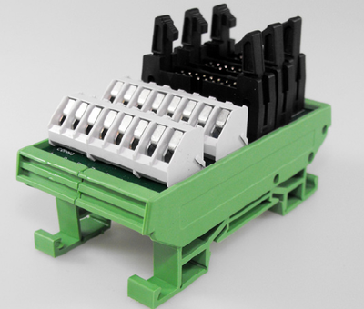
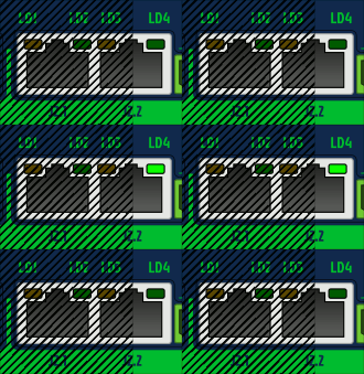
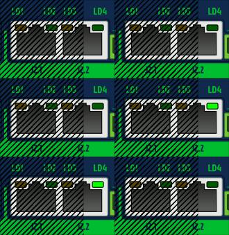
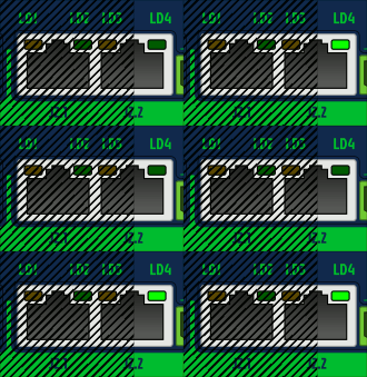
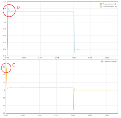
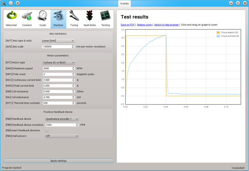
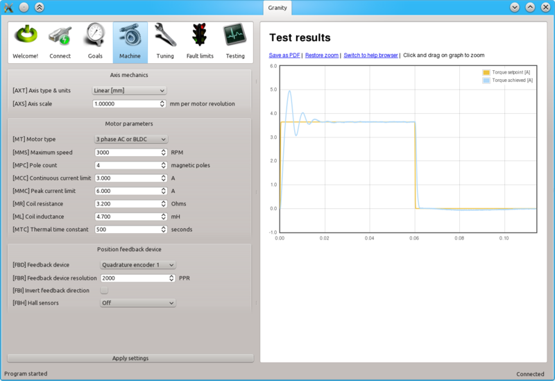
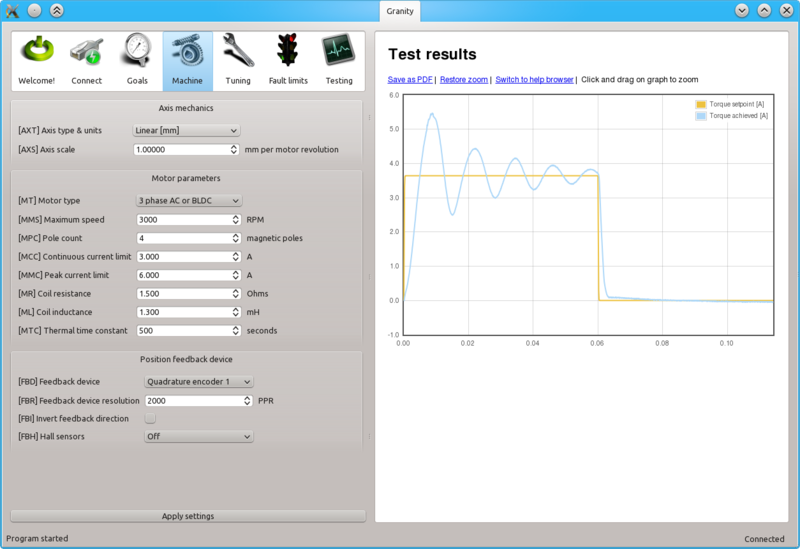
IONI user guidebook
This page collect most of the IONI & IONICUBE user guide articles as a single page.
Introduction to IONI
| IONI | |
|---|---|
 | |
| Device type | Servo & stepping motor drive |
| Model number | IONI-11K000, IONI-11K200 |
| Supported motors | AC, DC, BLDC, Linear, Stepper |
| Control modes | Position, Velocity, Torque |
| Status | Active production, started 2015 |
| Electrical | |
| DC supply voltage | 5 - 54 VDC (except 5 - 58 VDC in IONI Pro HC) |
| Output current range | 0.1 - 15A IONI, 0.1 - 18A IONI Pro, 0.1 - 25A IONI Pro HC |
| Setpoint signals | Pulse and direction, PWM, Analog, SimpleMotion V2 |
| Feedback devices | Quadrature encoder, SinCos encoder |
| General | |
| Configuration tool | Granity |
| Web site | Granite Devices IONI |
| Compliance | CE (EMC & LVD directives) |
| 3D model | |

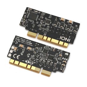
IONI is a digital motor drive designed for driving AC/BLDC and DC servo motors and steppers. IONI allows controlling motors in all three operating modes: position control, velocity control and torque control (torque mode only with servo motors). Applications of such control methods include
- Position control, such as CNC, robotics and 3D printing
- Velocity control, such as spindles or feeders
- Force / torque control, such as racing simulator wheel
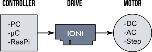
Commands to IONI drive can be delivered in many formats and from many sources, such as PC, PLC, microcontroller (i.e. Arduino, MBED and OEM boards) or embedded computers like Raspberry Pi. IONI understands several forms of setpoint commands:
- Step & direction digital signals (typical stepper drive interface, good for position control)
- Analog +/-10V signal (good for speed or torque control)
- PWM signal (good for speed or torque control)
- RS485 serial bus (talks SimpleMotion V2 bus protocol, open source library available)
Supported motors
As motor is not included, make sure that you have, or obtain a motor that is compatible with IONI. Learn more about motor types.
Servo motor requirements
- Permanent magnet brush-DC, AC, brushless or linear motor
- Motor voltage rating 12-60 VDC (IONI supply voltage is 5 - 52 VDC)
- Motor current rating 0.1 - 25A (choose drive model accordingly, IONI Pro HC, maximum output is 25A, IONI Pro 18A, and IONI 15A)
- Servo motor must be equipped with an supported feedback device (position sensor / encoder).
See Motor compatibility guide for more details.
Stepping motor requirements
- Two-phase stepping motor with 0.5 - 15A current rating, no feedback device needed. Can be used in position and velocity control mode. Torque mode not possible. Stepper voltage rating is irrelevant, but generally lower voltage & higher current stepper is better.
Unsuitable/non-optimum motors
- Any non-permanent magnet motors: induction AC motor or DC motor with field coil - will not work
- Cheapest grade DC motor, such as one extracted from power drill - might not give satisfying performance
- Motor with very high voltage, such as 200 VAC AC servo motor - it will work if it has incremental encoder feedback, but maximum rotation speed is limited due to drive voltage. Consider Argon servo drive for motors above 100 volts rating.
Features
State of the Art
- High dynamic range torque control
- Wide range motor support, from DC, BLDC, AC and Linear, from 5 W to 500 W
- High functional density and cost efficiency
- 3-level PWM output with reduced motor heating
- Automatically measures motor inductance and resistance for easy setup
- Anticogging / torque ripple compensation
Control
- Input setpoint signals including pulse and direction, quadrature, analog and PWM
- Multidrop & multiaxis capable real-time SimpleMotion V2 field bus for setup & control
- Internal axis homing function with sensorless hard-stop operating mode
Protections & Ruggedness
- Safe torque off
- Prevent machine damage via I²t (motor temperature modeling), blocked motion and tracking error detection
- Industry leading ruggedness: over current, short circuit, over voltage, under voltage and over temperature protections, data/communication error detection
- Warranty 24 months
- Charge pump enable input for safety
Applications
- Industrial servo & stepping motor control
- Robotics
- Industry 4.0 systems
- Testing equipment
- CNC
- Haptics
- Racing & flight simulators
- Pick'n'place machines
- Defense systems
Functionality and specifications
See main article IONI specifications.
Documentation & user guides
See the main article IONI & IONICUBE user guide.
Availability
Shipping worldwide at Granite Devices web shop.
IONI specifications
This page lists official functional, electrical and physical specifications of the IONI Servo Drive.| This page contains official specifications of a Granite Devices product. For security reasons contents, this Wiki page is protected thus modifiable by Granite Devices staff only. |
Device variations
IONI is available in three different models. See also IONI device model comparison.
- IONI
- Standard model
- IONI Pro
- Advanced model, additional features and increased current range
- IONI Pro HC
- Same features as IONI Pro, except higher current and voltage range
Main functionality
| Function | Description |
|---|---|
| Servo/stepping motor drive | Closed loop control of various types of servo motors by sinusoidal field oriented control with dead-time distortion correction and high dynamic range torque control.
|
| Control modes |
|
| Setpoint types |
See setpoint signal / reference inputs list
|
| Closed loop | Cascaded control loops (PIV):
|
| Feed-forwards | Feed-forwards working in velocity & position control modes:
|
| Homing | Integrated homing function for position control mode:
|
| Feedback devices | See feedback devices list |
| Safety |
|
| Protections |
|
| Power supply |
|
| Motor output current1 |
|
| Commissioning |
|
| Compliance |
Products are in conformity with the:
The following harmonized standards and technical specifications have been applied:
Notes:
|
| Reliability |
|
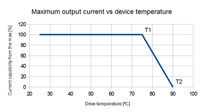
1) Currents achievable continuously only with with sufficient coolant air flow. Without forced cooling, typically 30-45% of the maximum range can be driven continuously. Despite of this, maximum current is available for short periods of time even without cooling. Current is automatically throttled on temperature rise to protect the drive.
Mechanical
| Property | Value | Units |
|---|---|---|
| Dimensions | 70.5 × 37 × 7.5 (W×H×D) | mm |
| Weight | 14.0 ± 0.5 | g |
| Drawings | |
|
| Pinout | IONI connector pinout |
Environment
| Property | Value | Units |
|---|---|---|
| Operating temperature | -10...+75, non condensing | °C |
| Storage temperature | -30...+90, non condensing | °C |
| Humidity | 0-95 non-condensing | % |
| Power dissipation | 0.3-15¹ | W |
¹) Power dissipation is output current and input voltage related.
Power supply
| Supply2 | Input voltage | Input current typ | Input current max |
|---|---|---|---|
| Logic power | 5 VDC +/- 10%4 | 0.1 - 0.2 A | 0.3 A |
| Motor power | 5 - 52 VDC3 (IONI, IONI Pro), 5 - 55 VDC 3 (IONI Pro HC) | 0 - 23.5 A1 | 23.5 A1 |
1) Estimating true current or power consumption based on this table may be difficult as current demand typically varies greatly and and almost completely depends on motor load conditions.
2) Both logic and motor supplies are required.
3) Possible to use from 5 VDC upwards, however short circuit protection feature is lost below 12 VDC.
4) IONICUBE motherboards provide on-board 5V regulator and accepts 24 VDC logic supply voltage. With IONICUBE no 5V supply is needed.
Motor output
| Property | Value | Units | Remarks |
|---|---|---|---|
| Supported motors | AC, BLDC, DC, Linear | Permanent magnet motors only | |
| Continuous output current | 0-151 (IONI), 0-181 (IONI Pro), 0-251 (IONI Pro HC) | A (peak value of sine) | User settable limit |
| Peak output current | 0-151 (IONI), 0-181 (IONI Pro), 0-251 (IONI Pro HC) | A (peak value of sine) | User settable current limit. |
| Maximum effective motor phase output voltage |
|
| |
| Switching frequency | 20.0 | kHz | |
| Maximum modulation depth | 95 | % | Maximum effective output is 95% of HV DC bus voltage. |
| Torque control bandwidth (typ.) | 1-3.3 | kHz | Motor coil dependent |
| Torque control cycle time | 50.0 | µs | |
| Position & velocity control cycle time | 400 | µs | |
| Power conversion efficiency | 93-97 | % | Under typical conditions |
| Motor inductance range @ 48 VDC | 0.2-25 | mH | |
| Motor inductance range @ 24 VDC | 0.1-25 | mH | |
| Motor power range | 0.01 - 0.5 | kW | |
| AC commutation frequency | 0-400 | Hz | Not capped, may achieve up to 2 kHz |
1) Maximum current is obtainable only for short periods without active air cooling. Drive automatically throttles current limit if drive temperature rises beyond 75 Celsius. Output current capacity reduces linearly between 75 and 90 degrees Celsius from the maximum to zero.
Regenerative resistor
IONI has a dedicated 3.3V logic level output for regenerative resistor control. The logic signal can be externally fed to a switch component (such as MOSFET) to drive external regenerative resistor to prevent overvoltage during rapid motor decelerations.
Feedback devices
Status of feedback device support
| Feedback device type | Status | Electrical interface |
|---|---|---|
| Quadrature incremental encoder | Standard feature | Differential 3-5.5V (RS422), Single ended 3-5.5V (CMOS,TTL,open collector) |
| Hall sensors | Standard feature | Single ended 3-5.5V (CMOS,TTL,open collector). Differential signals accepted. |
| Analog SinCos encoder | Standard feature in IONI Pro | 1 V p-p signal, user selectable 16X, 64X or 256X resolution interpolation factor (note 1). Automatic signal gain and offset calibration (info about Lissajous tuning). |
| Serial SSI absolute encoder | Standard feature in IONI Pro, see more info | RS422/RS485 |
| Serial BiSS absolute encoder | Standard feature in IONI Pro, see more info | RS422/RS485 |
1) The final resolution will be 4*line_count*interpolation_factor. I.e. with 1000 lines/electrical cycles per revolution SinCos encoder, the supported resolutions are 64000, 256000 and 1024000 counts per revolution. SinCos encoder can be also used without interpolation (4*line_count resolution).
Quadrature & SinCos encoder electrical properties
| Property | Value | Units | Remarks |
|---|---|---|---|
| Encoder count rate |
|
MHz | After 4x decoding, digitally filtered |
| SinCos encoder input frequency |
|
MHz | Max theoretical count rate at 256X interpolation becomes 1MHz*4*256 = 1024 MHz, however parameter Over speed faultFEV accepted value range might limit the achievable count rate to 75 MHz. |
| Supply voltage | 4.8-5.2 | V | Supplied externally (can share same voltage with drive logic supply) |
Setpoint signal / reference inputs
| Setpoint signal type | Status | Electrical interface |
|---|---|---|
| Analog | Standard feature |
|
| Pulse and direction | Standard feature |
Maximum step rate
|
| Quadrature | Standard feature |
Maximum quadrature frequency (count rate)
|
| PWM | Standard feature |
|
| Serial communication | Standard feature | SimpleMotion V2 real-time serial bus with open source SDK. Connect through RS485 or USB. |
| EtherCAT | Under development | Realized with add-on board, EtherFOX |
See also:
Inputs / outputs
List of I/O's
- Setpoint inputs
- Two digital channels (pulse/dir, quadrature or PWM)
- One +/-10V analog channel (differential, 2 wires)
- Digital inputs
- Switch inputs (3 channels): home switch, positive travel limit switch, negative travel limit switch
- Status control inputs (3 channels): enable, clear faults, STO
- Feedback inputs
- Quadrature encoder (3 channels differential, where 2 channels capable of 12 bit analog sampling)
- Hall sensors (3 channels)
- Digital outputs (3.3V logic level)
- Regenerative brake control output (external power switch needed, such as MOSFET)
- Holding brake control output (external power switch needed, such as MOSFET)
- Status indication outputs (3 channels): fault stop, servo ready, tracking error warning
- Serial comminication interfaces
- RS485 for SimpleMotion V2
Electrical characteristics
- Digital inputs accept standard signal levels 2.7 - 5.5 VDC, except STO and Enable inputs accept 4 - 26 VDC.
- Digital outputs provide 3.3 VDC signal level
- Analog inputs accept +-/10 VDC (+/- 12 VDC max) referenced to GND
Detailed properties
For detailed pin specific description and electrical ratings, see IONI connector pinout.
Communication
| Property | Value | Units |
|---|---|---|
| Communication protocol | SimpleMotion V2 | |
| Default bitrate | 460.8 | kBPS |
| Supported high bit rates | 1, 2, 3, 4, 4.5 | MBPS |
| Maximum number of SMV2 devices chained in a single bus | 32 | pcs |
| Command throughput | Up to 20000 | Commands/s |
Safety
| Feature | Properties | Remarks |
|---|---|---|
| Safe torque off |
Reaction time from STO2 signal voltage going below 2 volts to de-energized motor is maximum 5 ms. |
|
| Control error detection |
|
|
| Electrical safety |
| |
| Overload safety |
|
Warnings
| Exceeding ratings may affect drive operation and cause instability or even damage the drive or other equipment. Damaged equipment may pose danger to users. |
| Specifications are subject to change without notice |
IONI pinout
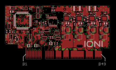
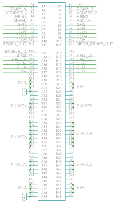
IONI card edge connector fits into a standard PCI-Express 8X socket connector. This page lists electrical and functional specifications of each pin.
Pinout
| Color |
|---|
| Power pin |
| Input pin |
| Output pin |
| Mixed or other purpose |
The pinout of IONI drive is provided in the following table.
- I/O and low voltage signals
| Pin | Signal name | Pin | Signal name | |
|---|---|---|---|---|
| A1 | GND | B1 | 5V_IN | |
| A2 | RS485_A | B2 | RS485_B | |
| A3 | ADDRSEL1 | B3 | ADDRSEL2 | |
| A4 | HSIN1 | B4 | HSIN2 | |
| A5 | ANAIN- | B5 | ANAIN+ | |
| A6 | GPI1 | B6 | GPI2 | |
| A7 | GPI3 | B7 | GPI4 | |
| A8 | GPO1 | B8 | GPO2 | |
| A9 | GPO3 | B9 | GPO4 | |
| A10 | GPO5 | B10 | GPI5 | |
| A11 | REGEN_OUT | B11 | MECH_BRAKE_OUT | |
| A12 | ENABLE_IN | B12 | Reserved/NC | |
| A13 | STO2 | B13 | HALL_W | |
| A14 | HALL_V | B14 | HALL_U | |
| A15 | A- | B15 | A+ | |
| A16 | B- | B16 | B+ | |
| A17 | C- | B17 | C+ |
- Power signals
| Pin | Signal name | Pin | Signal name | |
|---|---|---|---|---|
| A18-A22 | GND | B18 | Not connected | |
| A23 | Not connected | B19-B22 | HV+ | |
| A24-A27 | PHASE1 | B23 | Not connected | |
| A28 | Not connected | B24-B27 | PHASE2 | |
| A29-A37 | PHASE3 | B28 | Not connected | |
| A38 | Not connected | B29-B37 | PHASE4 | |
| A39-A43 | PHASE1 | B38 | Not connected | |
| A44 | Not connected | B39-B43 | PHASE2 | |
| A45-A49 | GND | B44 | Not connected | |
| B45-B49 | HV+ |
- Connection to motor
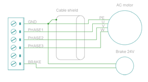
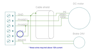
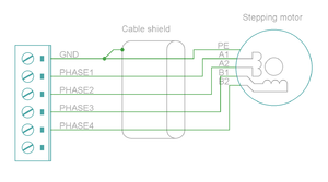
| Signal name | AC/BLDC motor | Brush DC motor | Stepping motor |
|---|---|---|---|
| GND | Connect motor cable shield and motor frame to power GND | ||
| PHASE1 | U (some motors R) | Armature + | Coil A.1 |
| PHASE2 | V (some motors S) | Armature - | Coil A.2 |
| PHASE3 | W (some motors T) | Connect to PHASE2 | Coil B.1 |
| PHASE4 | Not connected | Connect to PHASE1 | Coil B.2 |
Note 1: pins marked as Not connected are left empty for to make larger clearance for high voltage signals. Leave these pins unconnected on motherboard designs.
Note 2: Each power signal is present in two pin groups (internally parallel) and these signals should be wired parallel on motherboard.
Signal assignment
General purpose I/O (GPI/GPO)
The table below summarizes the default functions for GPIO pins.
| Connecting GPI/GPO's are not mandatory. All of the same functions may be also accessed via SimpleMotion V2 interface. |
| Signal name | Function | Used for | Remarks |
|---|---|---|---|
| GPI1 | Home switch | Homing reference switch (optional), can also disable homing, or use Hard-stop homing without switch | Note 1 |
| GPI2 | Enable positive feed | Axis positive direction end limit switch (optional) | Normally closed switch. When switch is open, motion/force in positive direction is prevented. 1 |
| GPI3 | Enable negative feed | Axis negative direction end limit switch (optional) | Normally closed switch. When switch is open, motion/force in negative direction is prevented. 1 |
| GPI4 | Clear faults | Rising logic edge on this pin will clear fault state of drive | In IONICUBE mode, also rising edge of enable signal will clear faults. |
| GPI5 | Start homing | Rising logic edge on this pin will start homing if homing is enabled | |
| GPO1 | Servo ready | Use to indicate controller that drive is ready | Logic 1 when drive has been initialized, enabled and ready to follow setpoint commands. If homing is enabled, then servo ready will be logic 1 after homing is successfully completed. |
| GPO2 | Tracking error warning | Use to indicate controller when drive is having difficulties following the setpoint before a tracking fault occurs | Logic 1 when tracking error (position or velocity, depending on control mode) is greater than 1/8 of configured fault trigger level. |
| GPO3 | Fault state (active low) | Use to indicate controller that drive is stopped due to fault state | In IONICUBE mode GPO3 goes logic 0 after when enable signal is set low (for Mach3 compatibility). GPO3 is open drain type to allow wired and connection. |
| GPO4 | 2-way travel allowed | Use to indicate controller when axis is allowed to move in both directions (i.e. any limit switches not hit or axis lies within an optional homing defined limited travel range) |
|
| GPO5 | Reserved | Feel free to request custom signal from Granite Devices support to be added in this output. For example fan control or custom status output. Changes can be made in customer specific firmware. |
1) Connect switch between GND and GPIn pin
See also Drive status & fault bits explained.
Setpoint signals
Setpoint mode is selected by software with parameter Setpoint inputCRI and behavior is affected by parameters Setpoint smoothingCIS, Setpoint multiplierMUL, Setpoint dividerDIV, Setpoint offset nullingCAO and Enable direction inputCED.
| Drive listens setpoint commands also always through SimpleMotion V2 interface regardess of Setpoint inputCRI paramter setting. |
| Signal name | Function | Used for | Remarks |
|---|---|---|---|
| HSIN1 | High speed digital input 1 | Depending on setpoint mode, can be either:
| |
| HSIN2 | High speed digital input 2 | Depending on setpoint mode, can be either:
| |
| ANAIN- | Differential analog negative input | Used for analog setpoint mode | Setpoint voltage is the voltage difference between ANAIN+ and ANAIN- |
| ANAIN+ | Differential analog positive input | Used for analog setpoint mode |
Feedback device signals
| Signal name # | Electrical type (in most feedback device modes) | Alternate electrical type (in some feedback device modes) | Connection with various feedback devices |
|---|---|---|---|
| HALL_W | Digital input W | Hall sensor input, phase W | |
| HALL_V | Digital input V | Hall sensor input, phase V | |
| HALL_U | Digital input U | Hall sensor input, phase U | |
| A- | Differential input A- | Analog input A- | Quadrature encoder (A channel)/SinCos A |
| A+ | Differential input A+ | Analog input A+ | |
| B- | Differential input B- | Analog input B+ | Quadrature encoder (B channel)/SinCos B |
| B+ | Differential input B+ | Analog input B- | |
| C- | Differential input C- | Quadrature encoder index channel (Z channel) | |
| C+ | Differential input C+ | ||
| In case of single-ended encoder, connect encoder's A, B, Z only to drive's A+, B+ and C+ and leave drive's A-, B- and C- unconnected. |
| With differential Hall sensor (which provides U+, U-, V+, V-, W+ and W-, connect only sensor's U+, V+ and W+ to drive's HALL_U/V/W. |
| Never connect sensor negative outputs (A-/B-/C-/U-/V-/W-) to GND. Connect them to drive's A-/B-/C- or leave unconnected. |
| Feedback devices with differential signaling may use varying naming schemes of signal pairs. For example differential signal X (which contains two electrical wires) may be denoted as: X+ and X-, or X and \X or X and X. In this Wiki we mark them X+ and X-. Some Fanuc encoders have quadrature signals named as PCA, /PCA, PCB, /PCB, PCZ and /PCZ which are equivalent to A, B and Z signal pairs. |
Other signals
| Signal name | Function | Used for | Remarks |
|---|---|---|---|
| REGEN_OUT | Regenerative resistor control output | Use to control optional regenerative resistor to prevent excessive voltage generation in HV DC bus during motor deceleration. | A buffer circuit is needed for resistor, such as a logic level MOSFET. See example schematic here. |
| MECH_BRAKE_OUT | Mechanical holding brake control output | Use to control optional holding brake of motor | A buffer circuit is needed to drive a solenoid brake, such as a logic level MOSFET. See example schematic here. |
| ENABLE_IN | Drive enable input signal (always required) | Use to enable drive and allow motor to initialize and operate | Accepts up to 24V voltage level, but works also with 5V level signal. (1) |
| STO2 | Safe torque off input signal (always required) | Use to allow motor to produce torque (activate power stage) | Accepts up to 24V voltage level, but works also with 5V level signal. STO is inactive (allows torque) when logic high is supplied. (1) |
(1) ENABLE_IN and STO2 are not 3.3V compatible, 4.5-26V signal is required to drive logic true state into them.
Electrical ratings
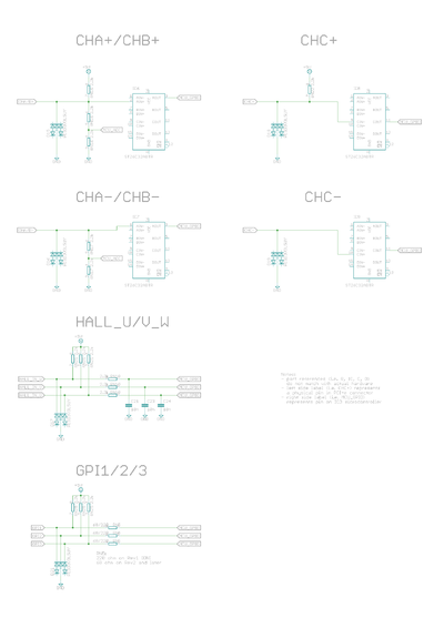
| Signal names | Allowed input voltages/output voltage | Internal input/output impedance (Ω) | Internal pull impedance (Ω) |
|---|---|---|---|
| 5V_IN | 5V +/-10% | - | - |
| HV+ | 0 – 55 V | - | - |
| RS485_A/B | RS485 serial bus, 2.7-5.5V signal level | >10k | - |
| ADDRSEL1, ADDRSEL2 | External address setting pull-down resistors to ground (minimum 1 kΩ). See chapter Selecting device address below. | - | 2.2k pull-up to 3.3V |
| HSIN1, HSIN2 | Logic low -0.3-1.0V, logic high 2.7-5.5V | - | 2.2k pull-up to 3.3V |
| ANAIN-, ANAIN+ | +/- 11V | 8k | - |
| GPI1...GPI4 | Logic low -0.3-1.0V, logic high 2.7-5.5V | - | 2.2k pull-up to 5V |
| GPI5 | Logic low -0.3-1.0V, logic high 2.7-5.5V | - |
|
| GPO1,2,4,5 | Logic low 0V, logic high 3.3V | 220 | - |
| GPO3 | Depends on Electrical interface Electrical interfaceCEI parameter: In IONICUBE mode it is an open drain output, pulled to 0V with 220 ohm impedance or pulled to 3.3V with pull-up (allow wired and connection of multiple drives). In other modes it is push-pull output (like GPO1,2,4,5) | 220 | ~20-50k pull-up to 3.3V |
| MECH_BRAKE_OUT | Logic low 0V, logic high 3.3V | 220 | - |
| REGEN_OUT | Logic low 0V, logic high 3.3V | 220 | - |
| ENABLE_IN | Logic low -0.3-2.0V, logic high 4.5-26V | 5k | 10k pull-down to GND |
| STO2 | Logic low -0.3-2.0V, logic high 4.5-26V | 8k | 20k pull-down to GND |
| HALL_U/V/W | Logic low -0.3-1.0V, logic high 2.7-5.5V | - | 2.2k pull-up to 5V |
| A/B/C+ | RS422 receiver, 2.7-5.5V signal level | - | 2.2k pull-up to 5V |
| A/B/C- | RS422 receiver, 2.7-5.5V signal level | - | 1.9k pull to 1.9V |
Electrical interface modes (software selectable)
IONI supports various function mappings to I/O signals and is selectable through Granity CEI Electrical interface parameter. The differences between modes are:
| Mode | Description | Effects (change of operation compared to Standard in this mode) |
|---|---|---|
| Standard | The default mode | I/O assignments as described in pinout |
| IONICUBE (CNC applications) | Mode for IONICUBE that is compatible with parallel port CNC controllers such as Mach3 and LinuxCNC software.
Not recommended with IONICUBE 1X as GPO3/fault output will not work then. |
|
| SimuCUBE | Mode for SimuCUBE motherboard for force feedback simulator systems. |
|
Selecting device address
When accessing drive through SimpleMotion V2 bus, each device in the bus should be assigned to different address between 1 to N. Device address is a sum of hardware setting and software parameter SimpleMotion bus address offsetSMO. The address of device is determined at the moment of logic voltage power on and will become by sum of hardware setting and SMO.
Hardware setting is set by connecting a resistor between ADDRSELx and GND by method defined in article IONI SimpleMotion address selection (ADDRSEL).
Software selecting address
When having more than four devices in the same bus, or for example chaining multiple IONICUBE 1X motherboards (where all of them have address 1), it is necessary to utilize software parameter SimpleMotion bus address offsetSMO. Procedure for setting unique address for each device with SMO:
- Disconnect or unpower all other devices that the ones with already unique address (i.e. have only one IONICUBE connected to SM bus, or powered on)
- Connect to drive with Granity
- Adjust SMO parameter value so that device will receive a desired bus address. I.e. if using IONICUBE 1X, set SMO values 0, 1, 2, 3 to the different drives (drive addresses will become 1, 2, 3, 4). Or when IONICUBE (4 axis) is being used, set SMO values of drives on the first board 0, second board 4, third 8 etc (drive addresses will become 1 - 12).
- Save settings, disconnect and repeat the procedure for all drives.
Set-up overwies & first connection
This is the official and latest setup guide of IONI Servo Drive and IONICUBE motherboards. Read it through before installing or operating IONI series devices.| NOTE: This guide attempts to be as complete and precise as humanly possible, however it can never be perfect. Writers of this guide are not responsible if possible damages or losses caused by mistakes or lacks of this guide. |
| IMPORTANT: IONI drive should be installed and operated only by qualified electricians. Dangerous voltages and mechanics may be involved and possibility of severe injury or even death is possible in case of installation or usage errors. |
Setup process overview
Read trough the guide by following the outline on the top right side of the page and follow the hyper links to subtopics provided in the articles.
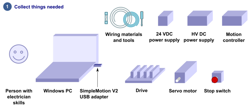
Read the page List of things needed for details.
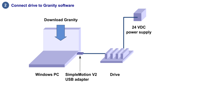
Connect drive to PC with SimpleMotion V2 USB adapter and Granity to test connection, upgrade firmware if necessary and to learn Granity. If you're already familiar with all this, you may skip this step. Read the article Making the first Granity connection.
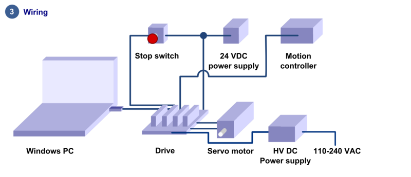
Carefully do the full wiring of the servo system. Consult an qualified electrician if necessary as dangerous voltages will be present. Before powering up, triple check everything by using multimeter to find short circuits. Read the main article Wiring.
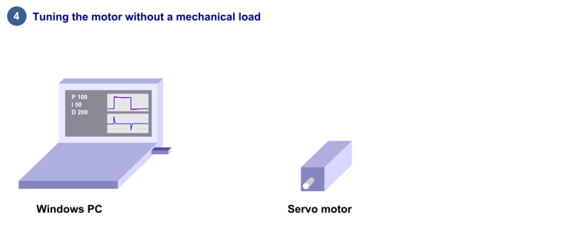
Power-up the system and connect again with Granity. Now set-up the motor to work as intended. See the main article Drive parameterization. If you already have a working configuration to your motor model, you may just load the settings file to the drive.
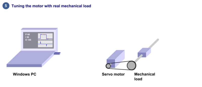
After motor and drive are fully functional, connect motor to the mechanical load and find the optimum velocity or position control gains. Read the main article Servo motor tuning guide.
Troubleshooting
In case of troubles, refer to the articles in general troubleshooting category and IONI troubleshooting category.
| Read next |
List of items needed
- The list of necessary things to build a working servo system with IONI
- IONI drive and a compatible motherboard such as IONICUBE, IONICUBE 1X or a custom board
- SimpleMotion V2 USB adapter
- 1 or more RJ45 Ethernet cables (see details & examples)
- Regulated 24 VDC power supply, output capability at least 0.5A per motherboard
- Regulated or non-regulated 5-52 VDC power supply for motor power. Output capability depends on motor power draw. If unsure, then a good start is a power supply between 150 to 600 Watts for a multiaxis motherboard. As a reference, a typical 3 axis Nema 23 stepping motor system can be fed with a 150-200 W 48 V power supply. See:
- A IONI compatible motor
- Shielded power conductors as motor power cord. Non-shielded will also work but increase EMI and may be source of communication errors.
- Ferrite core EMI filters
- Motion controller. This may be also a software on a computer.
- Windows PC
- Optional but highly recommended items
- Emergency stop button (normally closed NC type) or equivalent
- Needed for high current motors (>5A average)
- A cooling fan
- Tools needed
- Screwdrivers
- Wire cutter
- Skills needed
- Qualified electrician skills
- Basic knowledge of servo systems
| Read next |
Making the first Granity connection
Follow the instructions to make the first Granity connection to IONI drive.Preparations
- Download and install the Granity software. Latest version can be downloaded from the link: Granity software for windows (approx 18 MB)
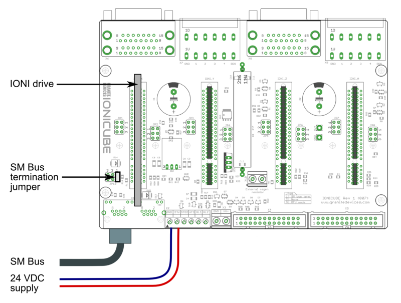
- Make a wiring similar to the image below
- With IONICUBE 4X revision 008 and lower, make sure that in the pinheader JP10 only position 1 has a jumper as depicted.
- With IONICUBE 4X revision 009 and higher, make sure that the switch S1 position 1 is ON and position 4 (DFU mode) is OFF.
- If you use a USB cable to connect (r. 009 and higher), turn also S1 position 2 and 3 ON.
- Connect IONICUBE to a PC
- with SimpleMotion V2 USB adapter and a straight Ethernet cable to connector X1, or
- with an USB cable without any adapters.
- Power up the 24 VDC power. Leds at the back of the IONI drive should start blinking (more about blinking sequences).
- Launch Granity software and:
- Go to Connect tab
- Ensure that "SimpleMotion V2 Adapter" is selected from dropdown menu called Communication interface device. (note 1)
- Click Connect to drive
- Once list of connected drives pop up, select the one you connected and click Open
Now if everything has gone well, you should see information about the drive model and serial number on the "Connect tab". Connection has been successfully tested and drive may be disconnected to proceed with next setup step.
Note 1) If multiple choices are named as "SimpleMotion V2 Adapter", then try each of them to find the correct one. Also if no adapters are found, try launching Granity software again as the list of adapter choices are updated only at program start-up.
IONICUBE Revision 1-8 (with jumpers)
IONICUBE Revision 9 and later (with DIP switch)
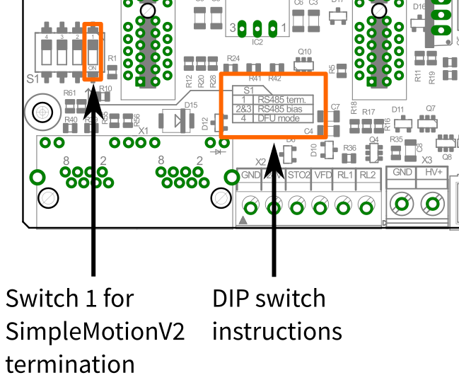
SM Bus termination switch position for IONICUBE revision 009 and higher. For typical single IONICUBE wiring, set switches 1-3 to ON position and 4th OFF position.
More information about the termination and biasing of the RS485 serial bus here: Wikipedia:RS-485.
| Read next |
Wiring overwiew
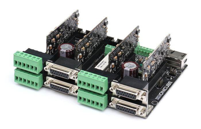
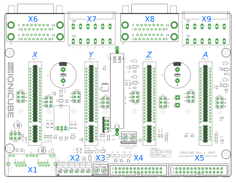
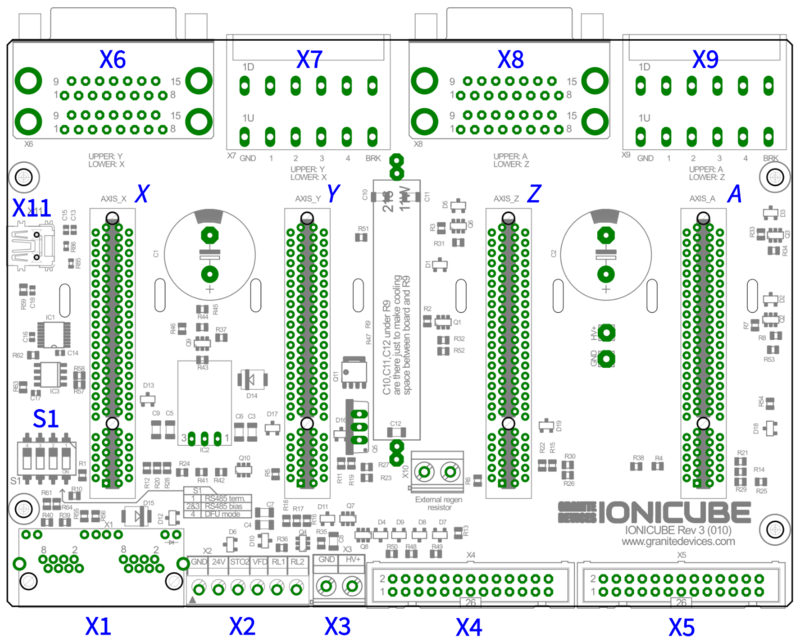
IONICUBE connectors
- X1
- Dual port RJ45 connector with SimpleMotion V2 interface. For pinout, seeSimpleMotion V2 port.
- X2
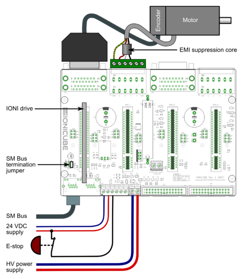
- 6 pin wire terminal for logic voltage supply, Safe torque off input, analog output and relay driver outputs.
- X3
- Two pin wire terminal for HV DC bus supply.
- X4
- Main control and setpoint signal port consisting Enable input signal, Fault output signal, pulse and direction/quadrature/PWM setpoint inputs and digital outputs for home switch status. X4 is directly wired to conform most common parallel port style pulse & direction CNC controllers.
- X5
- Second control and setpoint signal port. This port consists analog setpoint signal inputs and additional digital I/O.
- X6
- These are the feedback device connector for X (lower) and Y (upper) axis motors
- X7
- These are the power and holding brake output connector for X (lower) and Y (upper) axis motors
- X8
- These are the feedback device connector for Z (lower) and A (upper) axis motors
- X9
- These are the power and holding brake output connector for Z (lower) and A (upper) axis motors
- X10
- A connector for an optional external regenerative resistor. IONICUBE has on-board regenerative resistor that is sufficient for most installations.
- IONI_X, IONI_Y, IONI_Z, IONI_A
- Card-edge connectors for IONI drives
| Before inserting or removing IONI drives from IONICUBE, remove all power from it and discharge it's capacitors. To discharge remaining energy (~voltage) from capacitors, short circuit GND to HV+ by a conductor and measure that there is no DC voltage left between GND and HV+ terminals. Even few volts left to HV DC bus is known to cause permanent damage to IONICUBE when drives are plugged. |
Front side connectors
Front side connectors consist X6, X7, X8 and X9. These connectors are the interface towards motors (motor power and feedback devices).

Names of power and feedback ports. I.e. X9A means upper floor connector of X9 and X9B the lower floor of X9. View from plug side of the board.
Legend
| Color |
|---|
| Supply pin |
| Input pin |
| Output pin |
X7 and X9 pinout
These are the power output and holding brake output connector for motors
| Pin number | Signal name | AC/BLDC motor | Brush DC motor | Stepping motor |
|---|---|---|---|---|
| 1 | GND | Ground for cable shield and an optional motor holding brake coil | ||
| 2 | PHASE1 | U (some motors R) | Armature + | Coil A.1 |
| 3 | PHASE2 | V (some motors S) | Armature - | Coil A.2 |
| 4 | PHASE3 | W (some motors T) | Armature - | Coil B.1 |
| 5 | PHASE4 | Not connected | Armature + | Coil B.2 |
| 6 | BRAKE | Optional 24V motor holding brake coil | ||
Motor & brake wiring schematics
| An easy way to verify correctness of two phase stepper connection: unplug the 6 pin connector and then measure resistance between phases 1-2 and 3-4. Multimeter should show the same resistance for both cases (typically 0.1 - 5 ohms). Also when measuring between phases 1-3, 1-4, 2-3 and 2-4, the multimeter should indicate open circuit. |
X6 and X8 pinout
X6 and X8 are the feedback device connectors of motors
| Pin # | Pin name | Electrical type (in most feedback device modes) | Quadrature encoder | SinCos encoder | BiSS-C encoder | SSI encoder | AMS SSI encoder |
|---|---|---|---|---|---|---|---|
| Shell | GND | Earth/case | |||||
| 1 | HALL_W | Hall sensor digital input, phase W | - | - | - | ||
| 2 | HALL_V | Hall sensor digital input, phase V | - | - | - | ||
| 3 | HALL_U | Hall sensor digital input, phase U | - | - | - | ||
| 4 | GND | Encoder supply ground | |||||
| 5 | B- | Differential input B- | Channel B- | SinCos input B- | - | - | - |
| 6 | B+ | Differential input B+ | Channel B+ | SinCos input B+ | - | - | - |
| 7 | A- | Differential input A- | Channel A- | SinCos input A- | - | - | - |
| 8 | A+ | Differential input A+ | Channel A+ | SinCos input A+ | - | - | - |
| 9 | 5V_OUT | Encoder supply 5V output | |||||
| 10 | GND | Encoder supply ground | |||||
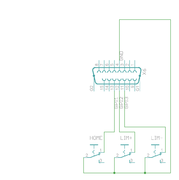
| 11 | GPI3 | Axis negative direction end limit switch (optional). Normally closed (NC) switch is highly recommended for safety reasons. Connect it between this pin and GND pin. Normally open (NO) switch can be used, and the switch polarity can be changed with Limit switch polarityLSP. |
Clock/MA- | Clock- | CLK | ||
| 12 | GPI2 | Axis positive direction end limit switch (optional).Normally closed (NC) switch is highly recommended for safety reasons. Connect it between this pin and GND pin. Normally open (NO) switch can be used, and the switch polarity can be changed with Limit switch polarityLSP. |
Clock/MA+ | Clock+ | CSn | ||
| 13 | GPI1 | Axis home switch switch (optional). Normally closed (NC) switch is highly recommended for safety reasons. Connect it between this pin and GND pin. Normally open (NO) switch can be used, and the switch polarity can be changed with Home switch or hard stop search direction (Home switch polarity)HMS. |
DO | ||||
| 14 | C- | Differential input C- | Index channel Z- | Index channel Z+ | Data/SLO- | Data- | - |
| 15 | C+ | Differential input C+ | Index channel Z+ | Index channel Z+ | Data/SLO+ | Data+ | - |
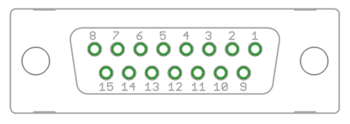
| Pin layout | Female D-sub 15 connector as it appears from outside of drive. Note: counterpart (male) connector has mirrored pin layout if viewed from pin side, and same layout if viewed from soldering side. | ||||||
| Especially with long encoder cables, it might be necessary to add encoder line termination resistors, see Terminating differential encoder lines. |
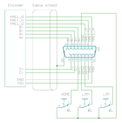
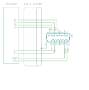
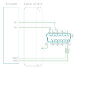
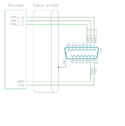
Examples of feedback device and switch wiring
| In case of single-ended encoder, connect encoder's A, B, Z only to drive's A+, B+ and C+ and leave drive's A-, B- and C- unconnected. |
| With differential Hall sensor (which provides U+, U-, V+, V-, W+ and W-, connect only sensor's U+, V+ and W+ to drive's HALL_U/V/W. |
| Never connect sensor negative outputs (A-/B-/C-/U-/V-/W-) to GND. Connect them to drive's A-/B-/C- or leave unconnected. |
| Feedback devices with differential signaling may use varying naming schemes of signal pairs. For example differential signal X (which contains two electrical wires) may be denoted as: X+ and X-, or X and \X or X and X. In this Wiki we mark them X+ and X-. Some Fanuc encoders have quadrature signals named as PCA, /PCA, PCB, /PCB, PCZ and /PCZ which are equivalent to A, B and Z signal pairs. |
Back side connectors
| Never connect an Ethernet to X1. While it uses similar connector and cabling, it is electrically incompatible with Ethernet. Devices may be permanently damaged by mixing Ethernet and SimpleMotion V2. |
| Do now wire SimpleMotion V2 ports with crossover RJ45 cables (see details). Always use straight/non-crossover patch cables. If unsure about what is the type of your RJ45 cable, don't use it. |
X2 pinout
X2 is 6 pin wire terminal for logic voltage supply, Safe torque off input, analog output and relay driver outputs.
| Pin number | Signal name | Usage |
|---|---|---|
| 1 | GND | Ground |
| 2 | 24V | 24V logic supply |
| 3 | STO | Safe torque off input (this pin also available in X1, as defined in SimpleMotion V2 port |
| 4 | VFD | 0-12V analog output where voltage level is proportional to PWM duty cycle on pin PWM on X4. PWM frequency must be between 100 and 10000 Hz. |
| 5 | RL1 | Relay coil driver output 1. When RLIN1 on X4 is logic high, RL1 is pulled to GND by an open collector circuit. When RLIN1 is low, RL1 is floating (max 24V). When connecting a relay that has 24VDC coil between RL1 and supplied 24V, no external free-wheeling diode is needed. Output current rating is max 500 mA. |
| 6 | RL2 | Relay coil driver output 2. When RLIN2 on X4 is logic high, RL2 is pulled to GND by an open collector circuit. When RLIN1 is low, RL2 is floating (max 24V). When connecting a relay that has 24VDC coil between RL2 and supplied 24V, no external free-wheeling diode is needed. Output current rating is max 500 mA. |
X3 pinout
X3 is two pin wire terminal for HV DC bus supply.
| Pin number | Signal name | Usage |
|---|---|---|
| 1 | GND | Ground |
| 2 | HV+ | Motor power supply, HV DC bus (see IONI drive voltage range spec) |
See also:
| If using switching power supply (SMPS) as motor power supply, external rectifier diodes are needed to protect the power supplies. See See IONI power supply schemes. |
X4 pinout
X4 is main control and setpoint signal port consisting Enable input signal, Fault output signal, pulse and direction/quadrature/PWM setpoint inputs and digital outputs for home switch status. X4 is directly wired to conform most common parallel port style pulse & direction CNC controllers.
| Pin number in header | Pin number in D25 cable | Signal name | Typical usage | Pin number in header | Pin number in D25 cable | Signal name | Typical usage | |
|---|---|---|---|---|---|---|---|---|
| 1 | 1 | ENABLE | Enable all axis (with or without chargepump) | 2 | 14 | PWM | PWM input for VFD analog output | |
| 3 | 2 | HSIN1_X | Pulse/step input X | 4 | 15 | GPO4_A | Limit switch output A | |
| 5 | 3 | HSIN2_X | Direction input X | 6 | 16 | RLIN1 | Controls RL1 state | |
| 7 | 4 | HSIN1_Y | Pulse/step input Y | 8 | 17 | RLIN2 | Controls RL2 state | |
| 9 | 5 | HSIN2_Y | Direction input Y | 10 | 18 | GND | Ground | |
| 11 | 6 | HSIN1_Z | Pulse/step input Z | 12 | 19 | GND | ||
| 13 | 7 | HSIN2_Z | Direction input Z | 14 | 20 | GND | ||
| 15 | 8 | HSIN1_A | Pulse/step input A | 16 | 21 | GND | ||
| 17 | 9 | HSIN2_A | Direction input A | 18 | 22 | GND | ||
| 19 | 10 | STOP_OUT | Fault on any axis or E-stop (active low). Note: this is IONI's GPO3 signals connected in parallel between all axis / wired-or configuration. | 20 | 23 | GND | ||
| 21 | 11 | GPO4_X | Limit switch output X | 22 | 24 | GND | ||
| 23 | 12 | GPO4_Y | Limit switch output Y | 24 | 25 | GND | ||
| 25 | 13 | GPO4_Z | Limit switch output Z | 26 | N/A | Not connected | ||
| Pin layout | 
| |||||||
| Connect only to 3.3V or 5V logic circuits go any GPI, GPO and HSIN pins. Most of X4 & X5 pins are directly routed to IONI drive pins and IONI electrical ratings apply. |
Alternative setpoint signals
Setpoint mode is selected by software with parameter Setpoint inputCRI and behavior is affected by parameters Setpoint smoothingCIS, Setpoint multiplierMUL, Setpoint dividerDIV, Setpoint offset nullingCAO and Enable direction inputCED.
| Drive listens setpoint commands also always through SimpleMotion V2 interface regardess of Setpoint inputCRI paramter setting. |
| Signal name | Function | Used for | Remarks |
|---|---|---|---|
| HSIN1 | High speed digital input 1 | Depending on setpoint mode, can be either:
| |
| HSIN2 | High speed digital input 2 | Depending on setpoint mode, can be either:
| |
| ANAIN- | Differential analog negative input | Used for analog setpoint mode | Setpoint voltage is the voltage difference between ANAIN+ and ANAIN- |
| ANAIN+ | Differential analog positive input | Used for analog setpoint mode |
X5 pinout
X5 is a second control and setpoint signal port in addition to X4. This port consists analog setpoint signal inputs and additional digital I/O.
| Pin number in header | Pin number in D25 cable | Signal name | Typical usage | Pin number in header | Pin number in D25 cable | Signal name | Typical usage | |
|---|---|---|---|---|---|---|---|---|
| 1 | 1 | GND | 2 | 14 | +5V_OUT | 5V supply from IONICUBE ^2 | ||
| 3 | 2 | ANAIN-_X | +/-10V analog input X | 4 | 15 | ANAIN+_X | +/-10V analog input X | |
| 5 | 3 | ANAIN-_Y | +/-10V analog input Y | 6 | 16 | ANAIN+_Y | +/-10V analog input Y | |
| 7 | 4 | ANAIN-_Z | +/-10V analog input Z | 8 | 17 | ANAIN+_Z | +/-10V analog input Z | |
| 9 | 5 | ANAIN-_A | +/-10V analog input A | 10 | 18 | ANAIN+_A | +/-10V analog input A | |
| 11 | 6 | GPO1_X | For pin function, refer to IONI connector pinout | 12 | 19 | GPI4_X | For pin function, refer to IONI connector pinout | |
| 13 | 7 | GPO1_Y | 14 | 20 | GPI4_Y | |||
| 15 | 8 | GPO1_Z | 16 | 21 | GPI4_Z | |||
| 17 | 9 | GPO1_A | 18 | 22 | GPI4_A | |||
| 19 | 10 | GPO5_X | 20 | 23 | GPI5_X | |||
| 21 | 11 | GPO5_Y | 22 | 24 | GPI5_Y | |||
| 23 | 12 | GPO5_Z | 24 | 25 | GPI5_Z | |||
| 25 | 13 | GPO5_A | 26 | N/A | GPI5_A | |||
| Pin layout | 
| |||||||
Application example
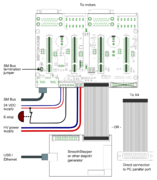
Follwing image shows typical installation schemes for pulse/direction controlled systems, typically found in PC CNC applications.A typical connection with parallel port style CNC controller such as Mach3/Mach4/LinuxCNC. A 26 pin ribbon cable may be directly connected to PC parallel port or to equivalent pinout step/dir generator such as SmoothStepper.
| Read next |
IONICUBE 4X wiring
IONICUBE connectors
- X1
- Dual port RJ45 connector with SimpleMotion V2 interface. For pinout, seeSimpleMotion V2 port.
- X2
- 6 pin wire terminal for logic voltage supply, Safe torque off input, analog output and relay driver outputs.
- X3
- Two pin wire terminal for HV DC bus supply.
- X4
- Main control and setpoint signal port consisting Enable input signal, Fault output signal, pulse and direction/quadrature/PWM setpoint inputs and digital outputs for home switch status. X4 is directly wired to conform most common parallel port style pulse & direction CNC controllers.
- X5
- Second control and setpoint signal port. This port consists analog setpoint signal inputs and additional digital I/O.
- X6
- These are the feedback device connector for X (lower) and Y (upper) axis motors
- X7
- These are the power and holding brake output connector for X (lower) and Y (upper) axis motors
- X8
- These are the feedback device connector for Z (lower) and A (upper) axis motors
- X9
- These are the power and holding brake output connector for Z (lower) and A (upper) axis motors
- X10
- A connector for an optional external regenerative resistor. IONICUBE has on-board regenerative resistor that is sufficient for most installations.
- IONI_X, IONI_Y, IONI_Z, IONI_A
- Card-edge connectors for IONI drives
| Before inserting or removing IONI drives from IONICUBE, remove all power from it and discharge it's capacitors. To discharge remaining energy (~voltage) from capacitors, short circuit GND to HV+ by a conductor and measure that there is no DC voltage left between GND and HV+ terminals. Even few volts left to HV DC bus is known to cause permanent damage to IONICUBE when drives are plugged. |
Front side connectors
Front side connectors consist X6, X7, X8 and X9. These connectors are the interface towards motors (motor power and feedback devices).

Names of power and feedback ports. I.e. X9A means upper floor connector of X9 and X9B the lower floor of X9. View from plug side of the board.
Legend
| Color |
|---|
| Supply pin |
| Input pin |
| Output pin |
X7 and X9 pinout
These are the power output and holding brake output connector for motors
| Pin number | Signal name | AC/BLDC motor | Brush DC motor | Stepping motor |
|---|---|---|---|---|
| 1 | GND | Ground for cable shield and an optional motor holding brake coil | ||
| 2 | PHASE1 | U (some motors R) | Armature + | Coil A.1 |
| 3 | PHASE2 | V (some motors S) | Armature - | Coil A.2 |
| 4 | PHASE3 | W (some motors T) | Armature - | Coil B.1 |
| 5 | PHASE4 | Not connected | Armature + | Coil B.2 |
| 6 | BRAKE | Optional 24V motor holding brake coil | ||
Motor & brake wiring schematics
| An easy way to verify correctness of two phase stepper connection: unplug the 6 pin connector and then measure resistance between phases 1-2 and 3-4. Multimeter should show the same resistance for both cases (typically 0.1 - 5 ohms). Also when measuring between phases 1-3, 1-4, 2-3 and 2-4, the multimeter should indicate open circuit. |
X6 and X8 pinout
X6 and X8 are the feedback device connectors of motors
| Pin # | Pin name | Electrical type (in most feedback device modes) | Quadrature encoder | SinCos encoder | BiSS-C encoder | SSI encoder | AMS SSI encoder |
|---|---|---|---|---|---|---|---|
| Shell | GND | Earth/case | |||||
| 1 | HALL_W | Hall sensor digital input, phase W | - | - | - | ||
| 2 | HALL_V | Hall sensor digital input, phase V | - | - | - | ||
| 3 | HALL_U | Hall sensor digital input, phase U | - | - | - | ||
| 4 | GND | Encoder supply ground | |||||
| 5 | B- | Differential input B- | Channel B- | SinCos input B- | - | - | - |
| 6 | B+ | Differential input B+ | Channel B+ | SinCos input B+ | - | - | - |
| 7 | A- | Differential input A- | Channel A- | SinCos input A- | - | - | - |
| 8 | A+ | Differential input A+ | Channel A+ | SinCos input A+ | - | - | - |
| 9 | 5V_OUT | Encoder supply 5V output | |||||
| 10 | GND | Encoder supply ground | |||||
| 11 | GPI3 | Axis negative direction end limit switch (optional). Normally closed (NC) switch is highly recommended for safety reasons. Connect it between this pin and GND pin. Normally open (NO) switch can be used, and the switch polarity can be changed with Limit switch polarityLSP. |
Clock/MA- | Clock- | CLK | ||
| 12 | GPI2 | Axis positive direction end limit switch (optional).Normally closed (NC) switch is highly recommended for safety reasons. Connect it between this pin and GND pin. Normally open (NO) switch can be used, and the switch polarity can be changed with Limit switch polarityLSP. |
Clock/MA+ | Clock+ | CSn | ||
| 13 | GPI1 | Axis home switch switch (optional). Normally closed (NC) switch is highly recommended for safety reasons. Connect it between this pin and GND pin. Normally open (NO) switch can be used, and the switch polarity can be changed with Home switch or hard stop search direction (Home switch polarity)HMS. |
DO | ||||
| 14 | C- | Differential input C- | Index channel Z- | Index channel Z+ | Data/SLO- | Data- | - |
| 15 | C+ | Differential input C+ | Index channel Z+ | Index channel Z+ | Data/SLO+ | Data+ | - |
| Pin layout | Female D-sub 15 connector as it appears from outside of drive. Note: counterpart (male) connector has mirrored pin layout if viewed from pin side, and same layout if viewed from soldering side. | ||||||
| Especially with long encoder cables, it might be necessary to add encoder line termination resistors, see Terminating differential encoder lines. |
Examples of feedback device and switch wiring
| In case of single-ended encoder, connect encoder's A, B, Z only to drive's A+, B+ and C+ and leave drive's A-, B- and C- unconnected. |
| With differential Hall sensor (which provides U+, U-, V+, V-, W+ and W-, connect only sensor's U+, V+ and W+ to drive's HALL_U/V/W. |
| Never connect sensor negative outputs (A-/B-/C-/U-/V-/W-) to GND. Connect them to drive's A-/B-/C- or leave unconnected. |
| Feedback devices with differential signaling may use varying naming schemes of signal pairs. For example differential signal X (which contains two electrical wires) may be denoted as: X+ and X-, or X and \X or X and X. In this Wiki we mark them X+ and X-. Some Fanuc encoders have quadrature signals named as PCA, /PCA, PCB, /PCB, PCZ and /PCZ which are equivalent to A, B and Z signal pairs. |
Back side connectors
| Never connect an Ethernet to X1. While it uses similar connector and cabling, it is electrically incompatible with Ethernet. Devices may be permanently damaged by mixing Ethernet and SimpleMotion V2. |
| Do now wire SimpleMotion V2 ports with crossover RJ45 cables (see details). Always use straight/non-crossover patch cables. If unsure about what is the type of your RJ45 cable, don't use it. |
X2 pinout
X2 is 6 pin wire terminal for logic voltage supply, Safe torque off input, analog output and relay driver outputs.
| Pin number | Signal name | Usage |
|---|---|---|
| 1 | GND | Ground |
| 2 | 24V | 24V logic supply |
| 3 | STO | Safe torque off input (this pin also available in X1, as defined in SimpleMotion V2 port |
| 4 | VFD | 0-12V analog output where voltage level is proportional to PWM duty cycle on pin PWM on X4. PWM frequency must be between 100 and 10000 Hz. |
| 5 | RL1 | Relay coil driver output 1. When RLIN1 on X4 is logic high, RL1 is pulled to GND by an open collector circuit. When RLIN1 is low, RL1 is floating (max 24V). When connecting a relay that has 24VDC coil between RL1 and supplied 24V, no external free-wheeling diode is needed. Output current rating is max 500 mA. |
| 6 | RL2 | Relay coil driver output 2. When RLIN2 on X4 is logic high, RL2 is pulled to GND by an open collector circuit. When RLIN1 is low, RL2 is floating (max 24V). When connecting a relay that has 24VDC coil between RL2 and supplied 24V, no external free-wheeling diode is needed. Output current rating is max 500 mA. |
X3 pinout
X3 is two pin wire terminal for HV DC bus supply.
| Pin number | Signal name | Usage |
|---|---|---|
| 1 | GND | Ground |
| 2 | HV+ | Motor power supply, HV DC bus (see IONI drive voltage range spec) |
See also:
| If using switching power supply (SMPS) as motor power supply, external rectifier diodes are needed to protect the power supplies. See See IONI power supply schemes. |
X4 pinout
X4 is main control and setpoint signal port consisting Enable input signal, Fault output signal, pulse and direction/quadrature/PWM setpoint inputs and digital outputs for home switch status. X4 is directly wired to conform most common parallel port style pulse & direction CNC controllers.
| Pin number in header | Pin number in D25 cable | Signal name | Typical usage | Pin number in header | Pin number in D25 cable | Signal name | Typical usage | |
|---|---|---|---|---|---|---|---|---|
| 1 | 1 | ENABLE | Enable all axis (with or without chargepump) | 2 | 14 | PWM | PWM input for VFD analog output | |
| 3 | 2 | HSIN1_X | Pulse/step input X | 4 | 15 | GPO4_A | Limit switch output A | |
| 5 | 3 | HSIN2_X | Direction input X | 6 | 16 | RLIN1 | Controls RL1 state | |
| 7 | 4 | HSIN1_Y | Pulse/step input Y | 8 | 17 | RLIN2 | Controls RL2 state | |
| 9 | 5 | HSIN2_Y | Direction input Y | 10 | 18 | GND | Ground | |
| 11 | 6 | HSIN1_Z | Pulse/step input Z | 12 | 19 | GND | ||
| 13 | 7 | HSIN2_Z | Direction input Z | 14 | 20 | GND | ||
| 15 | 8 | HSIN1_A | Pulse/step input A | 16 | 21 | GND | ||
| 17 | 9 | HSIN2_A | Direction input A | 18 | 22 | GND | ||
| 19 | 10 | STOP_OUT | Fault on any axis or E-stop (active low). Note: this is IONI's GPO3 signals connected in parallel between all axis / wired-or configuration. | 20 | 23 | GND | ||
| 21 | 11 | GPO4_X | Limit switch output X | 22 | 24 | GND | ||
| 23 | 12 | GPO4_Y | Limit switch output Y | 24 | 25 | GND | ||
| 25 | 13 | GPO4_Z | Limit switch output Z | 26 | N/A | Not connected | ||
| Pin layout | 
| |||||||
| Connect only to 3.3V or 5V logic circuits go any GPI, GPO and HSIN pins. Most of X4 & X5 pins are directly routed to IONI drive pins and IONI electrical ratings apply. |
Alternative setpoint signals
Setpoint mode is selected by software with parameter Setpoint inputCRI and behavior is affected by parameters Setpoint smoothingCIS, Setpoint multiplierMUL, Setpoint dividerDIV, Setpoint offset nullingCAO and Enable direction inputCED.
| Drive listens setpoint commands also always through SimpleMotion V2 interface regardess of Setpoint inputCRI paramter setting. |
| Signal name | Function | Used for | Remarks |
|---|---|---|---|
| HSIN1 | High speed digital input 1 | Depending on setpoint mode, can be either:
| |
| HSIN2 | High speed digital input 2 | Depending on setpoint mode, can be either:
| |
| ANAIN- | Differential analog negative input | Used for analog setpoint mode | Setpoint voltage is the voltage difference between ANAIN+ and ANAIN- |
| ANAIN+ | Differential analog positive input | Used for analog setpoint mode |
X5 pinout
X5 is a second control and setpoint signal port in addition to X4. This port consists analog setpoint signal inputs and additional digital I/O.
| Pin number in header | Pin number in D25 cable | Signal name | Typical usage | Pin number in header | Pin number in D25 cable | Signal name | Typical usage | |
|---|---|---|---|---|---|---|---|---|
| 1 | 1 | GND | 2 | 14 | +5V_OUT | 5V supply from IONICUBE ^2 | ||
| 3 | 2 | ANAIN-_X | +/-10V analog input X | 4 | 15 | ANAIN+_X | +/-10V analog input X | |
| 5 | 3 | ANAIN-_Y | +/-10V analog input Y | 6 | 16 | ANAIN+_Y | +/-10V analog input Y | |
| 7 | 4 | ANAIN-_Z | +/-10V analog input Z | 8 | 17 | ANAIN+_Z | +/-10V analog input Z | |
| 9 | 5 | ANAIN-_A | +/-10V analog input A | 10 | 18 | ANAIN+_A | +/-10V analog input A | |
| 11 | 6 | GPO1_X | For pin function, refer to IONI connector pinout | 12 | 19 | GPI4_X | For pin function, refer to IONI connector pinout | |
| 13 | 7 | GPO1_Y | 14 | 20 | GPI4_Y | |||
| 15 | 8 | GPO1_Z | 16 | 21 | GPI4_Z | |||
| 17 | 9 | GPO1_A | 18 | 22 | GPI4_A | |||
| 19 | 10 | GPO5_X | 20 | 23 | GPI5_X | |||
| 21 | 11 | GPO5_Y | 22 | 24 | GPI5_Y | |||
| 23 | 12 | GPO5_Z | 24 | 25 | GPI5_Z | |||
| 25 | 13 | GPO5_A | 26 | N/A | GPI5_A | |||
| Pin layout | 
| |||||||
Application example
Follwing image shows typical installation schemes for pulse/direction controlled systems, typically found in PC CNC applications.A typical connection with parallel port style CNC controller such as Mach3/Mach4/LinuxCNC. A 26 pin ribbon cable may be directly connected to PC parallel port or to equivalent pinout step/dir generator such as SmoothStepper.
IONICUBE 1X wiring
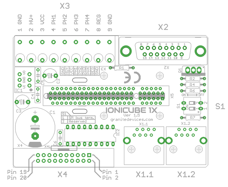
IONICUBE 1X connectors
- X1.1 and X1.2
- RJ45 connector with SimpleMotion V2 interface. For pinout, seeSimpleMotion V2 port.
- X2
- feedback device connector for motor
- X3
- 9 pin wire terminal for HV DC bus supply, logic voltage supply, regenerative resistor and motor power output.
- X4
- Control and setpoint signal port. Contains also output for motor solenoid holding brake.
- X5
- Card-edge connectors for IONI drive
| Before inserting or removing IONI drives from IONICUBE, remove all power from it and discharge it's capacitors. To discharge remaining energy (~voltage) from capacitors, short circuit GND to HV+ by a conductor and measure that there is no DC voltage left between GND and HV+ terminals. Even few volts left to HV DC bus is known to cause permanent damage to IONICUBE when drives are plugged. |
IONICUBE 1X connectors
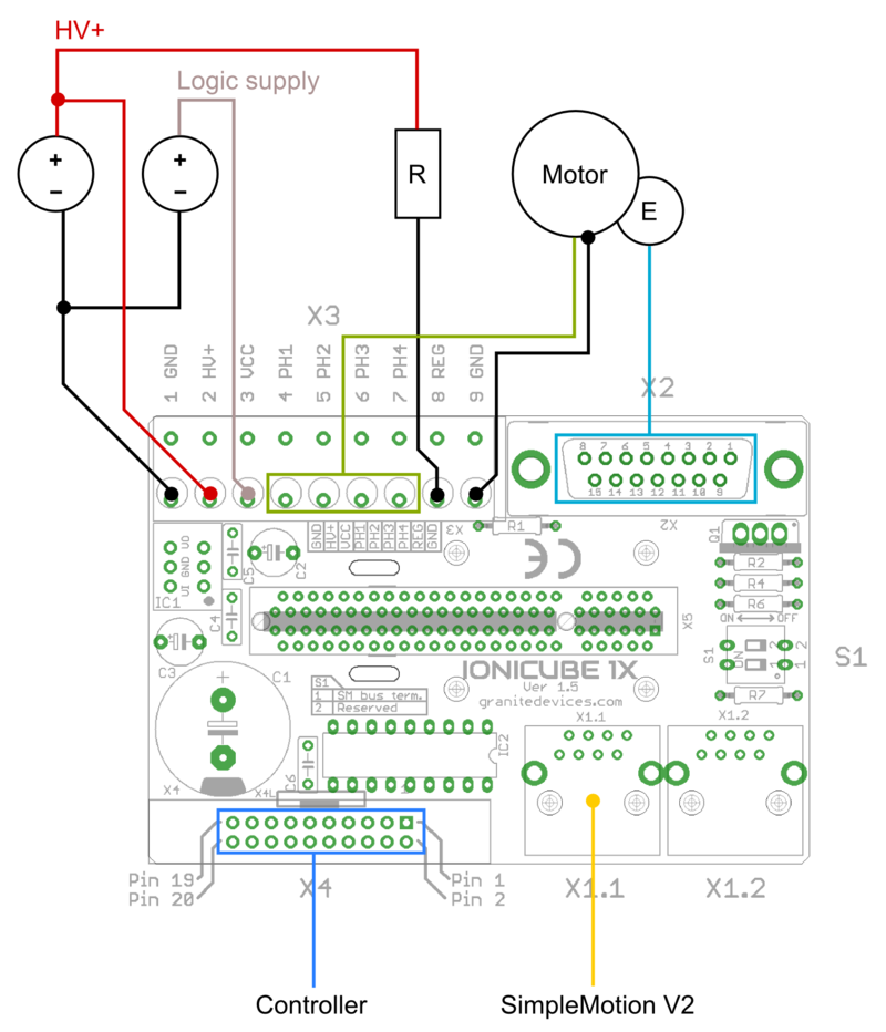
Wiring overview. R is regenerative resistor and E is encoder. In minimum working connection, wire 5V voltage to ENABLE and STO2 inputs into X4 pins (these two signals allow drive to be operated). Note: STO2 accepts voltage from 4.5 to 25 VDC but other digital inputs, such as ENABLE only between 2.7 to 5.5VDC.
| If using switching power supply (SMPS) as motor power supply, external rectifier diodes are needed to protect the power supplies. See See IONI power supply schemes. |
Legend
| Color |
|---|
| Supply pin |
| Input pin |
| Output pin |
X3 pinout
This is a wire terminal connector for power input and output
| Pin number | Signal name | Usage |
|---|---|---|
| 1 | GND | Ground |
| 2 | HV+ | Motor power supply, HV DC bus (see IONI drive voltage range spec) |
| 3 | VCC | 24V logic supply |
| 4 | PH1 (PHASE1) | Motor phase 1 (see wiring table below) |
| 5 | PH2 (PHASE2) | Motor phase 2 (see wiring table below) |
| 6 | PH3 (PHASE3) | Motor phase 3 (see wiring table below) |
| 7 | PH4 (PHASE4) | Motor phase 4 (see wiring table below) |
| 8 | REG | Regenerative resistor output |
| 9 | GND | Ground |
| Pin number | Signal name | AC/BLDC motor | Brush DC motor | Stepping motor |
|---|---|---|---|---|
| 1 | GND | Ground for cable shield and an optional motor holding brake coil | ||
| 4 | PHASE1 | U (some motors R) | Armature + | Coil A.1 |
| 5 | PHASE2 | V (some motors S) | Armature - | Coil A.2 |
| 6 | PHASE3 | W (some motors T) | Armature - | Coil B.1 |
| 7 | PHASE4 | Not connected | Armature + | Coil B.2 |
Motor & brake wiring schematics
Note: the images below are drawn for IONICUBE 4 axis version. IONICUBE 1X wiring is equivalent except there is no brake output in the X3. Brake output pin is located in X4.
| An easy way to verify correctness of two phase stepper connection: unplug the 6 pin connector and then measure resistance between phases 1-2 and 3-4. Multimeter should show the same resistance for both cases (typically 0.1 - 5 ohms). Also when measuring between phases 1-3, 1-4, 2-3 and 2-4, the multimeter should indicate open circuit. |
Regenerative resistor
Regenerative resistor is optional and may be connected between REG and HV+ terminals. The on board transistor is capable of carrying max 10 Amp current on regenerative resistor, so minimum allowed resistance can be calculated from: Rmin=HVvoltage/10. I.e. with 48VDC HV supply, the minimum resistance is 48V/10A = 4.8 Ohms. Suggested resistor power capability is 20-100 W.
| When multiple IONICUBE 1X's are connected to a shared HV supply, then it is typically sufficient to have regenerative resistor only in one IONICUBE 1X as it will help to prevent voltage build-up in the HV supply line. |
X2 pinout
X2 is the feedback device connector of motor
| Pin # | Pin name | Electrical type (in most feedback device modes) | Quadrature encoder | SinCos encoder | BiSS-C encoder | SSI encoder | AMS SSI encoder |
|---|---|---|---|---|---|---|---|
| Shell | GND | Earth/case | |||||
| 1 | HALL_W | Hall sensor digital input, phase W | - | - | - | ||
| 2 | HALL_V | Hall sensor digital input, phase V | - | - | - | ||
| 3 | HALL_U | Hall sensor digital input, phase U | - | - | - | ||
| 4 | GND | Encoder supply ground | |||||
| 5 | B- | Differential input B- | Channel B- | SinCos input B- | - | - | - |
| 6 | B+ | Differential input B+ | Channel B+ | SinCos input B+ | - | - | - |
| 7 | A- | Differential input A- | Channel A- | SinCos input A- | - | - | - |
| 8 | A+ | Differential input A+ | Channel A+ | SinCos input A+ | - | - | - |
| 9 | 5V_OUT | Encoder supply 5V output | |||||
| 10 | GND | Encoder supply ground | |||||
| 11 | GPI3 | Axis negative direction end limit switch (optional). Normally closed (NC) switch is highly recommended for safety reasons. Connect it between this pin and GND pin. Normally open (NO) switch can be used, and the switch polarity can be changed with Limit switch polarityLSP. |
Clock/MA- | Clock- | CLK | ||
| 12 | GPI2 | Axis positive direction end limit switch (optional).Normally closed (NC) switch is highly recommended for safety reasons. Connect it between this pin and GND pin. Normally open (NO) switch can be used, and the switch polarity can be changed with Limit switch polarityLSP. |
Clock/MA+ | Clock+ | CSn | ||
| 13 | GPI1 | Axis home switch switch (optional). Normally closed (NC) switch is highly recommended for safety reasons. Connect it between this pin and GND pin. Normally open (NO) switch can be used, and the switch polarity can be changed with Home switch or hard stop search direction (Home switch polarity)HMS. |
DO | ||||
| 14 | C- | Differential input C- | Index channel Z- | Index channel Z+ | Data/SLO- | Data- | - |
| 15 | C+ | Differential input C+ | Index channel Z+ | Index channel Z+ | Data/SLO+ | Data+ | - |
| Pin layout | Female D-sub 15 connector as it appears from outside of drive. Note: counterpart (male) connector has mirrored pin layout if viewed from pin side, and same layout if viewed from soldering side. | ||||||
| Especially with long encoder cables, it might be necessary to add encoder line termination resistors, see Terminating differential encoder lines. |
Examples of feedback device and switch wiring
| In case of single-ended encoder, connect encoder's A, B, Z only to drive's A+, B+ and C+ and leave drive's A-, B- and C- unconnected. |
| With differential Hall sensor (which provides U+, U-, V+, V-, W+ and W-, connect only sensor's U+, V+ and W+ to drive's HALL_U/V/W. |
| Never connect sensor negative outputs (A-/B-/C-/U-/V-/W-) to GND. Connect them to drive's A-/B-/C- or leave unconnected. |
| Feedback devices with differential signaling may use varying naming schemes of signal pairs. For example differential signal X (which contains two electrical wires) may be denoted as: X+ and X-, or X and \X or X and X. In this Wiki we mark them X+ and X-. Some Fanuc encoders have quadrature signals named as PCA, /PCA, PCB, /PCB, PCZ and /PCZ which are equivalent to A, B and Z signal pairs. |
X4 pinout
| This section is unfinished. Don't use until this notice is removed. |
X4 is main control and setpoint signal port consisting Enable input signal, Fault output signal, pulse and direction/quadrature/PWM setpoint inputs and digital outputs for home switch status. X4 is directly wired to conform most common parallel port style pulse & direction CNC controllers.
| Pin number in header | Signal name | Typical usage | Signal name | Typical usage | |
|---|---|---|---|---|---|
| 1 | GND | Ground | 2 | 5V_OUT | 5V output for optional external circuity |
| 3 | HSIN2 | Depending on setpoint mode, can be either:
|
4 | HSIN1 | Depending on setpoint mode, can be either:
|
| 5 | ANAIN+ | +/-10V analog setpoint input2 | 6 | ANAIN- | +/-10V analog setpoint input2 |
| 7 | GPI2 | Enable positive feed (also in X2)1 | 8 | GPI1 | Home switch input (also in X2)1 |
| 9 | GPI4 | Clear faults1 | 10 | GPI3 | Enable negative feed (also in X2)1 |
| 11 | REGEN_OUT | Regenerative resistor power switch state (redundant, IONICUBE 1X has internal power switch) | 12 | GPI5 | Start homing1 |
| 13 | MECH_BRAKE_OUT | Mechanical holding brake output3 | 14 | GPO5 | Reserved for future use1 |
| 15 | GPO4 | Limit switch output | 16 | GPO3 | Fault on any axis or E-stop (active low)1 |
| 17 | GPO2 | Tracking error warning1 | 18 | GPO1 | Servo ready1 |
| 19 | STO2 | Safe torque off input (this pin also present in X14) | 20 | ENABLE | Enable drive (with or without chargepump) (this pin also present in X14) |
1) For detailed pin function and alternative functions in various modes, refer to IONI connector pinout
2) Setpoint voltage is measured from the difference of voltage potentials between ANAIN+ and ANAIN-. Both ANAIN inputs must always lie within +/-12V from GND (meaning that controller's zero voltage reference, i.e. GND must be connected to the GND if drive to prevent voltage potentials from floating.
3) This output can directly drive a 24V solenoid brake (max 500mA) if VCC is supplied by 24 volts. In such case, connect brake wires between MECH_BRAKE_OUT and VCC.
4) The same pin is routed also to X1 connectors. Use ENABLE/STO2 pins of only either X4 or X1, not both.
| Connect X4 directly only to 3.3V or 5V logic systems. For 24V logic, see chapter below. |
X1 connector
X1 connectors are for SimpleMotion V2 bus which is used for drive configuration with Granity software and control over a multidrop capable serial data link. For pinout, see SimpleMotion V2 port.
| Never connect an Ethernet to X1. While it uses similar connector and cabling, it is electrically incompatible with Ethernet. Devices may be permanently damaged by mixing Ethernet and SimpleMotion V2. |
| Do now wire SimpleMotion V2 ports with crossover RJ45 cables (see details). Always use straight/non-crossover patch cables. If unsure about what is the type of your RJ45 cable, don't use it. |
DIP Switch S1 settings
On board switch S1 controls the SM bus termination. Set switch 1 to ON position if the IONICUBE 1X devie is the only device in a SM bus OR if it's the last device in device chain. All other cases, leave it OFF (in other words, if IONICUBE is chained to multiple SM bus devices and it's not the last device of the chain).
Using 24 Volt control signals
As many industrial environments use 24V signaling for logic, interfacing IONICUBE 1X has been designed to accept these voltages with help of external circuits:
- The GPOx outputs are NPN open collector type the pulling pin to GND when output is logic 1. GPO can be loaded up to same voltage level with logic supply voltage.
- If 24V logic accepts such NPN open collector output, wire directly
- If push/pull type output is needed, wire a pull-up resistor (i.e. 2200 Ohm or higher) between GPOx and 24V voltage
- Inputs are routed directly to IONI input pins that accept up to 5V directly. To extend the range, add a resistor divider network to reduce the voltage to accepted level. I.e. on each pin:
- 470 Ohm resistor from GPIx to GND, and
- 2200 Ohm GPIx to user 24V input signal
- That two-resistor circuit will reduce 24V level logic 1 to an acceptable ~4.2V level, while logic 0 will be ~0V.
Dimensions and mounting
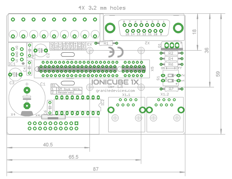
IONICUBE 1X can be mounted by screws to a base or with optional DIN rail clips to a standard DIN rail.
To mount in DIN rail, obtain 2 pcs of Phoenix Contact part number 1201578. Such part is available from many distributors including Digikey 277-2296-ND
.Mating connectors and accessories
Warning: Display title "IONI Mating connectors and accessories for IONI & IONICUBE" overrides earlier display title "IONI IONI & IONICUBE wiring (4 axis IONICUBE)".
This page lists examples of available mating connectors, accessories and spare parts for IONI drive together with IONICUBE four axis motherboard. Most parts or equivalents are available from large number of distributors. You may use http://www.findchips.com/ to search the same or similar parts from alternative distributors.Recommended shopping list
- Connectors and backshells for X6/X8 unless using a motor with pre-made encoder cables (like Granite Devices servo motors)
- X1 cable (RJ45 cable)
- X4/X5 connectors and flat cable
- A flat cable to D-Sub 25 connector if direct connection to parallel port based PC CNC software is desired
- EMI filters
- 24 VDC logic power supply
- HV DC bus power supply
See the list of example parts below.
Connectors
X6 & X8 connector
| Description | Manufacturer | Part number | Distributors and order codes |
|---|---|---|---|
| PLUG, D, SOLDER, 15WAY | MULTICOMP | 5501-15PA-02-F1 |
|
Accessories
| Description | Manufacturer | Part number | Distributors and order codes |
|---|---|---|---|
| D-SUB BACKSHELL, 15WAY | MH CONNECTORS | DPPK15-GREY-K |
|
X1 connector
Cable assemblies
Cable used for X1 should be shielded (S/FTP or FTP, not UTP) type.
| Description | Manufacturer | Part number | Distributors and order codes |
|---|---|---|---|
| Premium patch cable 0.5m | VIDEK | 3962-0.5 | Farnell 1525999 |
| Premium patch cable 1m | VIDEK | 3962-1 | |
| Premium patch cable 2m | VIDEK | 3962-2 | Farnell 1525753 |
| Premium patch cable 5m | VIDEK | 3962-5 | Farnell 1525755 |
| Premium patch cable 10m | VIDEK | 3962-10 | |
| Shielded patch cable 0.5m | VIDEK | 2992-0.5 | Farnell 1517504 |
| Shielded patch cable 1m | VIDEK | 2992-1 | |
| Shielded Patch cable 2m | VIDEK | 2992-2 | Farnell 1517506 |
| Shielded patch cable 5m | VIDEK | 2992-5 | Farnell 1517509 |
| Shielded patch cable 10m | VIDEK | 2992-10 | |
| Shielded patch cable 0.5m | Assman | A-MCSP-80005/B-R | Digikey A-MCSP-80005/B-R |
| Shielded patch cable 1m | Assman | A-MCSP-80005/Y-R | Digikey A-MCSP-80010/Y-R |
| Shielded patch cable 2m | Assman | A-MCSP-80020/Y-R | Digikey A-MCSP-80020/Y-R |
| Shielded patch cable 3m | Assman | A-MCSP-80050/Y-R | Digikey A-MCSP-80030/Y-R |
| Shielded patch cable 5m | Assman | A-MCSP-80050/Y-R | Digikey A-MCSP-80050/Y-R |
| Shielded patch cable 10m | Assman | A-MCSP-80050/Y-R | Digikey A-MCSP-80100/Y-R |
Accessories
| Description | Manufacturer | Part number | Distributors and order codes |
|---|---|---|---|
| RJ45 break-out board with DIN rail fixture (convert RJ45 to screw terminals). Helpful for wiring STO and Enable wires. | Camden boss | CIM/RJ45 | Farnell 2211819 |
X7 and X9 connector
These parts are included with IONICUBE 4 axis product.
| Description | Manufacturer | Part number | Distributors and order codes |
|---|---|---|---|
| 6 pole 5mm pitch terminal plug | FCI | 20020007-G061B01LF |
X4 and X5 connector
Mating connector type is 0.1" pitch 26 pin IDC ribbon cable socket, see example (pdf).
| Description | Manufacturer | Part number | Distributors and order codes |
|---|---|---|---|
| SOCKET, IDC, 2.54MM, 26WAY | AMPHENOL | T812126A100CEU |
|
| SOCKET, IDC, WITH S/RELIEF, 26WAY | MULTICOMP | MC6FD026-30P1 |
|
| FLAT CABLE 26 WAY | 3M | 3302/26 300SF | Digikey MC26M-5-ND |
Accessories
| Description | Manufacturer | Part number | Distributors and order codes |
|---|---|---|---|
| IDC terminal block, 26WAY | Camden boss | CIM/202426W-IDCS |
|
| FLAT CABLE TO D-SUB 25 CONNECTOR | Sullins | SDS103-PRW2-M25-SN00-211 | Digikey S9577-ND |
Electromagnetic interference filtering
| Description | Manufacturer | Part number | Distributors and order codes |
|---|---|---|---|
| EMI suppression core for low frequency band | Laird | LFB159079-000 | Digikey 240-2281-ND |
| EMI suppression core for medium frequency band | Laird | 28B0616-000 | Digikey 240-2306-ND |
Power supplies
Before making decision on power supplies, see:
24V low power logic supply
| Description | Manufacturer | Part number | Distributors and order codes |
|---|---|---|---|
| 24 VDC power supply | TDK-Lambda | LS35-24 | Digikey 285-1893-ND |
| 24 VDC DIN rail power supply | CUI Inc | VDRS-20-24 | Digikey 102-2152-ND |
HV DC high power motor supply
| Voltage | Power | Manufacturer | Part number | Distributors and order codes |
|---|---|---|---|---|
| 24 VDC | 150 W | Delta Electronics | PMT-24V150W1AA | Digikey 1145-1075-ND |
| 24 VDC | 200 W | Delta Electronics | PMT-24V200W1AM | Digikey 1145-1076-ND |
| Voltage | Power | Notes | ! Manufacturer | Part number | Distributors and order codes |
|---|---|---|---|---|---|
| 48 VDC | 150 W | Delta Electronics | PMT-48V150W1AA | Digikey 1145-1109-ND | |
| 48 VDC | 200 W | TDK-Lambda | LS200-48 | Digikey 285-1982-ND | |
| 48 VDC | 300 W | TDK-Lambda | RWS300B48 | Digikey 285-2294-ND | |
| 48 VDC | 320 W | Mean Well | RSP-320-48 | Granite Devices Store RSP-320-48 | |
| 48 VDC | 480 W | DIN rail mounting | Mean Well | NDR-480-48 | Granite Devices Store NDR-480-48 |
| 48 VDC | 480 W | 720 W peak output power capability, DIN rail mounting | Mean Well | SDR-480-48 | Mouser SDR-480-48 |
| 48 VDC | 480 W | Requires 3 phase AC power | XP Power | DNR480PS48-I | Digikey 1470-1102-ND
Farnell 1372704 |
| 48 VDC | 450 W | Not CE compliant (EU) | Mean Well | SE-450-48 | Findchips SE-450-48 |
| 48 VDC | 480 W | Delta Electronics | DRP048V480W1BN | Digikey 1145-1094-ND | |
| 48 VDC | 600 W | Not CE compliant (EU) | Mean Well | SE-600-48 | Findchips SE-600-48 |
| 48 VDC | 600 W | TDK-Lambda | RWS600B48 | Digikey 285-2298-ND | |
| 48 VDC | 960 W | Requires 3 phase AC power | XP Power | DNR960TS48-I | Digikey 1470-3050-ND
Farnell 1634807 |
| 48 VDC | 1000 W | XP Power | SHP1000PS48 | Digikey 1470-2226-ND |
| Read next |
Status LED indicators
Warning: Display title "IONI LED indicators" overrides earlier display title "IONI Mating connectors and accessories for IONI & IONICUBE".IONI has two on-board led indicators which have dedicated indicating tasks:- LED1 Motor control state indicator (green)
- LED2 Fault indicator (orange)
How to read indications
- LED1 and LED2 have programmed blinking sequences. Sequences consists series of short (S) and long (L) light pulses. For example LLS means the led will blink two long flashs and then one short flash. After sequence there will be a pause before the sequence repeats.
- LED1 and LED2 are independent and can show fault and motor state simultaneously. To easier reading sequence, cover one led with a thumb to be able to concentrate to one led.
- LED2 and shows the first fault occurred if multiple fault states are active simultaneously.
- LED1 and LED2 are flashing together if device is in a firmware upgrade mode (DFU).
List of all LED1 and LED2 sequences
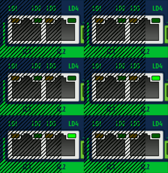
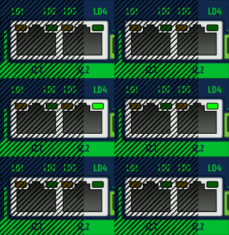
To see animated images, view this Wiki page in a web browser with animations enabled. The animations show Argon front panel, but the blinking sequences of IONI are equivalent when LED1=LD4 and LED2=LD3.
Faults
Only LED2 is being controlled by these faults, except in DFU mode when both leds blink together.
| Fault reason | LED sequence | LED sequence as text |
|---|---|---|
| Hardware | 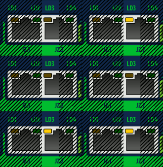 |
LLSS |
| Progral or memory | 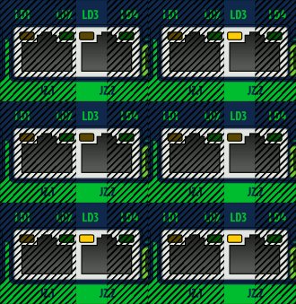 |
LSLL |
| Internal comm error (CRC) | 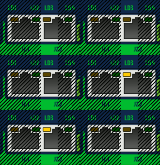 |
LSL |
| Initialization | 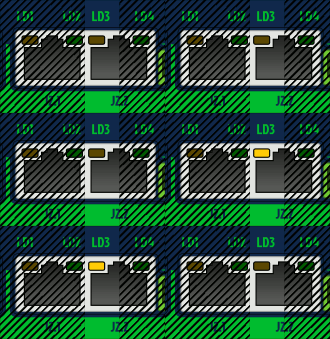 |
LSS |
| Over current | 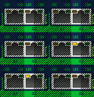 |
SLL |
| Over temperature | 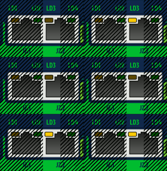 |
LSLS |
| Over voltage | 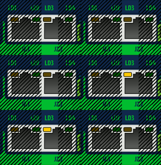 |
SLS |
| Following error | 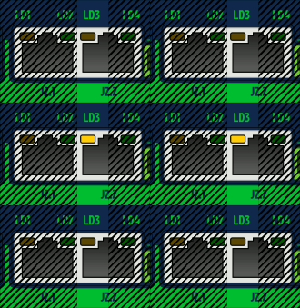 |
LS |
| Under voltage | 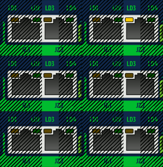 |
SL |
| Motion blocked or motor runaway |  |
SSL |
| Setpoint range exceeded | 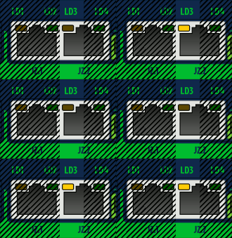 |
LSSL |
| SimpleMotion communication error | 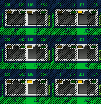 |
LSSS |
| Other/unknown, possibly configuration error such as motor mode Motor typeMT not selected | 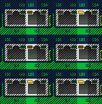 |
SSSL |
Motor control states
Only LED1 is being controlled by these states.
IONICUBE LED indicators
IONICUBE has four LED indicators that will are dedicated to:
- LED1
- Power on (24V supplied)
- LED2
- GPO1_X (LED on when GPO1_X is high)
- LED3
- Fault stop state (LED on when any of drives has fault stop state on)
- LED4
- Regenerative resistor is being driven
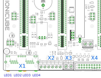
LED1-4 on IONICUBE
| Read next |
Drive parameterization
Warning: Display title "IONI parameterization" overrides earlier display title "IONI LED indicators".This article will describe how to set-up IONI parameters with Granity to make motor operational and ready for servo tuning.
Preparations and connection
As the goal is to parameterize and make motor operational, we should have:
- The drive and motor fully wired. However it's not required to have controller or braking resistor connected at this point.
- Be familiar with the operation and parameters of Granity. Make sure you have read Granity user guide.
- Granity connection working. See IONI & IONICUBE user guide/Making the first Granity connection
Walk-through of initial parametrization
In this chapter we walk-trough all Granity tabs and modify the parameter needed. This guide assumes that the drive is in factory defaults state (not configured before). Restore drive to factory state can be done by uploading a firmware file to the drive.
| Experimenting with drive parameters is (mostly) safe. If motor is attached to machine or bench for testing and nothing is attached to shaft (so motor can't jump but it can spin freely), then playing with all drive parameters can be regarded safe. The most important parameters are proper motor Peak current limitMMC and Continuous current limitMCC to avoid overheating of motor. If unsure of proper current limits, start with low values and increase gradually if motor stays cool. |
Connect tab
No other actions than connect to drive needed on this tab. Once connection successful, proceed to the next tab.
Goals tab
The factory defaults (torque control as control mode and serial only as setpoint) as well as the other defaults are the correct ones for beginning.
Machine tab
In this tab we configure the motor and its feedback device.
Axis mechanics
Parameters Axis type & unitsAXT and Axis scaleAXS affect only on the unit conversion of Granity parameters (such as acceleration/velocity limit unit conversions) and has no effect on drive operation.
Choose your axis type and scale, or leave them as defaults.
Motor
Find motor parameters from the motor data sheet/manufacturer specifications.
- Choose motor type from the drown down list Motor typeMT. If motor is linear type, see configuring linear servo motor. If setting up a stepping motor instead of servo motor, see Using stepping motor with IONI.
- Set motor Pole countMPC (non-brush DC motors only). If unsure, see Determining motor pole count.
- Set Maximum speedMMS of the motor, or alternatively the maximum allowed motor speed in the target application
- Set motor Peak current limitMMC and Peak current limitMMC current values. If non-brush DC motor type has been selected, then these are measured as the peak value of sine. See Motor peak and continuous current limits for description.
- Set Thermal time constantMTC. Motor thermal time constant value in seconds, used for thermal modeling of motor to avoid motor overheating with Peak current limitMMC. If not available, use formula 200*motor_weight (kg) as approximate, so a 2 kg motor would get a 400 second time constant. There is no guarantee of accuracy of this method.
- Setting motor Coil resistanceMR and Coil inductanceML values are required for proper drive operation. Do this by using the Granity's measurement function after drive is enabled and operating the first time. If this method fails, perform Tuning torque controller manually after initial parameters are set or find motor inductance & resistance values from your motor data sheet.
| As torque is directly proportional to motor current, it is advisable to set current limits lower at the beginning of testing. I.e. 50% of motor's rated current will produce 50% of motor's rated torque. |
| Using resistance & inductance measure function the recommended approach to set MR and ML parameters accurately even when motor data sheet would provide these values. This is because many data sheets unfortunately provide inaccurate values. Some manufacturers have apparently characterized motor inductance at high frequency range (hundreds of kHz) which typically gives a value more than 50% off from the real inductance. |
Feedback device
- Choose feedback device type from the drop down Feedback deviceFBD
- Set feedback device resolution. If Feedback deviceFBD is quadrature encoder, then manufacturers typically give resolution as pulses per revolution (PPR) or lines per revolution (LPR) which are the same thing and shall be entered directly into Feedback device resolutionFBR field. Some manufactures also call PPR as CPR.
- Configure the polarity of feedback device counting direction by Invert feedback directionFBI parameter. Motor and feedback device must have same electrical positive rotation direction to make a stable servo system. If your system shows no stability (instant following error after a motor "jump"), try changing this setting.
- Leave the Hall sensors Off from parameter Hall sensorsFBH during initial setup. Enable later if necessary (see when).
Tuning
Tuning tab contains feedback gain values for velocity and position control modes as well as torque bandwidth limit setting. Configuring these parameters are documented in Servo motor tuning guide. However, before proceeding into tuning, go through all other settings listed in this article.
Fault limits
Fault limits define the conditions in which drive is willing to operate. If condition is out of the set values, drive will enter into a fault state and stop motor control until errors are cleared.
Drive fault limits
These settings specify drive electrical condition such as supply voltage and over current tolerance.
- Leave Over current toleranceFOC value as default if no overcurrent faults occur. See Tuning torque controller if overcurrent faults occur.
- Set Over voltage fault thresholdFOV following way depending on your HV DC bus supply voltage. Set FOV value at least 10% higher than nominal HV DC bus voltage. For detailed guide of understanding FUV and FOV parameters, see page Configuring drive voltage limits FUV and FOV. Examples:
- 24 VDC regulated power supply, try value of 32 VDC
- 48 VDC regulated power supply, try value of 54 VDC
- Set Under voltage fault thresholdFUV so that drive will not trigger undervoltage fault during varying load of HV DC bus. Example:
- 24 VDC regulated power supply, try value of 19 VDC
- 48 VDC regulated power supply, try value of 35 VDC
- It is important to goal deviation faults (i.e. Goal faults filter timeFFT, Position tracking error thresholdFPT, Velocity tracking error thresholdFVT, Over speed faultFEV) as low as possible. Set them so that faults don't occur during normal operation but any anomaly or unexpected behavior will trigger them.
| If goal deviation faults are unnecessary high, drive may pose a danger in case of unexpected behavior. For example if motor starts running away full speed without command, then proper velocity fault threshold values may save from damage. |
| Overvoltage limit parameter FOV also determines the voltage level when drive starts driving current to the regenerative resistor. If you experience constant heating of the resistor, increase FUV value. |
Goal deviation faults
These faults adjust motor monitoring during operation. Drive will enter into fault state if motor condition deviates more than allowed from the desired condition. See Granity unit conversion before adjusting.
- Goal Goal faults filter timeFFT sets the time how fast Position tracking error thresholdFPT, Velocity tracking error thresholdFVT, Over speed faultFEV and Motion fault thresholdFMO faults react. Setting higher time value allows drive to continue operation over short deviations thus avoid false triggering. Set this from 0.0 to 0.2 seconds in the beginning.
- Set Position tracking error thresholdFPT according how much mechanical axis is allowed to deviate from the setpoint position in position control mode.
- Set Velocity tracking error thresholdFVT according how much motor or axis speed may may deviate from the velocity setpoint. This affects also in position mode as velocity controller is the intermediate step between torque and position controllers.
- Set Over speed faultFEV according to the maximum speed allowed for the motor or axis. Helps to stop motor if system goes totally out of control and speeds up spuriously.
- Leave Motion fault thresholdFMO as 0 (0 = disabled) for the beginning. Using nonzero value enables motion fault.
- Choose Limit switch functionLFS according to your preference. If other than Do nothing option requires that limit switches are installed and connected to J5 port. Note: at the moment Servo stop option is active in the drive firmware and will do nothing until FW upgrade enables it.
Testing tab
These settings does not affect drive operation, so nothing to be changed here at this point. These controls will be used for servo tuning purposes and fault analysis.
Enabling drive
In order to test any configuration you make, you need to set drive in enabled state. This involves that:
- Drive is powered on (logic & HV DC bus)
- Enable signal is powered.
- If no physical enable signal is wired, you may click Force enable drive from Connect tab to temporarily enable without physical signal. Note that Force enable will release (inactivate) if any of following physical inputs change state: Enable, Limit switches or Home switch.
- STO2 input is powered
- Motor typeMT is configured
- If Require software enableCEN is enabled, then also click Soft enable drive from Connect tab
Servo motor tuning
Tuning a servo motor is a compulsory task to make motor behave as desired and perform well during operation. Follow the Servo motor tuning guide.
Finishing touches
The last step of parameterization is to adapt settings to match the motion controller. Steps:
- Choose setpoint input Setpoint inputCRI to match your motion controller.
- If external motion controller with acceleration limit (such as CNC controller) is being used, then it is advised to set Acceleration limitCAL value to maximum of 32767 (unlimited acceleration) after motor tuning to enable motion tracking without delay. Use a limited acceleration value if drive is being used with pulse burst positioning or SimpleMotion V2 controller.
- If setpoint is too sensitive or not sensitive enough (such as limiting speed), then adjust setpoint scaling factory by adjusting Setpoint multiplierMUL and Setpoint dividerDIV.
- If setpoint signal is noisy or jittering, try enabling Setpoint smoothingCIS to smoothen it inside drive. However, leave Setpoint smoothingCIS disabled if setpoint tracking without any delay is desired.
- Set-up homing if required by application
| Read next |
Servo tuning basics
Driving a servo motor is much like driving a car. Driving a car has many similarities including the key concepts of torque, velocity and position control. Most of this happens in the driver's head the same way than a servo drive does with a motor.
For those who are already familiar with the basics, see the principles of real world servo motor drive from article Signal path of motor drive.
Driving (a.k.a servoing) a car
Driving a car to a destination is much like driving a servo motor to it's destination position. The analogies in between are:
| Car | Servo axis |
|---|---|
| Pedal (motor gasoline feed) | Torque setpoint (motor current feed) |
| Speed limit | Velocity setpoint |
| Target location | Position setpoint |
| Speed meter | Velocity feedback |
| Trip meter | Position feedback |
| Car driver | Servo drive |
The ultimate goal of driver is to get to the target. To achieve this, he follows the road (trajectory) at certain velocity and decelerates once target is being reached. Without knowing, the driver acts as servo controller where he:
- Controls car's velocity based on the speed meter value and speed limit
- Controls car's position based on trip meter's reading or by observing location trough the windshield
- All actions the driver makes, is based on comparing the setpoints and the actual state
Servo controller basics
Controller gains and a PI controller
Controller gain means sensitivity to change output due to tracking error (the difference between setpoint and feedback).
The simplest form of feedback based controller is a proportional gain controller (P controller) where output follows the formula output = Pgain*(setpoint-feedback). The problem of proportional gain controller is that it may never reach the setpoint because output starts approaching zero when the following error is reaching zero.
Because of this, it's better to add in integrating component to the controller (forming PI controller). Integrator accumulates the tracking error to a integrator variable. Integrator variable is like a bucket of water, when you add water, the water level rises and when you take out water, the level lowers. In controller the equation becomes: output = Pgain*(setpoint-feedback) + Igain*IntegralOf(setpoint-feedback).
The characteristics of feedback gain variables:
- P-gain - reacts instantly to the tracking error but can't eliminate tracking error completely
- I-gain - reacts slowly over time, adjusts output until tracking error is zero
When driving a car, human brain closely resembles the operation of a PI controller. For in-depth info about PI controllers and its variants, see the Wikipedia article PID controller.
Tuning the gains
Controller tuning means finding of the optimum gain values for the given system.
The proper gain values always depend on many aspects, especially the target system dynamic properties (such as motor properties, axis transmission ratios, inertias and masses). Change of properties introduces the requirement of tuning the gain values as gain values that work fine in one system may not behave satisfactory on a different system.
In servo drive case, this means that each motor type and mechanical axis need to be tuned separately. However, if axis and motors are identical, then the same gains should work equally.
Gain tuning (car) example
The following series of images illustrate an imaginary car driving scenario where the driver acts as velocity controller of the car. The magnitude of PI gain values equal the driver's aggressivity of controlling the pedal to reach the desired speed.
Low gains - sluggish response
If the gains are set too low, the system response tends to be sluggish and sometimes leave a static tracking error (not reaching setpoint in any time). In this imaginary case we could think PI gains to be P=20 I=10.
Too high gains - oscillation & instability
If the gains are set too high, the system becomes overshooting, oscillating and less stable. Here the comparable PI gains could be P=200 I=100
Optimum gains - only little overshoot
When the gains are tuned correctly, the response shows rapid response with low overshoot and no ringing or oscillations. The comparable gains here P=50 I=25.
Optimum gains with realistic setpoint - optimum response
The response can be improved further by introducing a limit to the slew rate of setpoint signal. The controller behaves optimally when the system is able to follow the setpoint continuously with little tracking error. In this case the gains could be same as before, P=50 I=25.
Real servo motor controller
See the principles of real world servo motor drive from article Signal path of motor drive.
| Read next |
Tuning torque controller
Torque controller tuning means finding the correct gain values for a torque controller inside the servo drive to achieve a proper response from a torque setpoint change.
| Torque controller inside drive is implemented by a PI controller where P and I gains are controlled proportionally by Coil inductanceML and Coil resistanceMR respectively. |
Direct inductance & resistance setting method
In Granity, there is no dedicated torque control PI gains as the software supports entering motor coil inductance and resistance where the suitable PI gains are calculated from.
Method 1 (preferred)
If you are using a drive model that supports automatic measurement of inductance and resistance, follow the instructions here.
Method 2
If the above measurement function is not available, and your motor comes with coil specifications containing phase-to-phase inductance and resistance values, then the only necessary step is to enter the given values into motor Coil resistanceMR and Coil inductanceML parameter fields. In case of troubles with this method, proceed with manual tuning method.
Manual tuning method
Manual tuning of torque controller is some times done in order to optimize the torque controller response or to find the correct motor Coil resistanceMR and Coil inductanceML parameters if unknown. Manual tuning also usually yields better torque response than the direct method which may help tuning of velocity or position tuning.
| If satisfactory performance was achieved by direct inductance & resistance setting method, you may skip the manual tuning method. |
In order to change torque tuning, one needs to change motor Coil resistanceMR and Coil inductanceML parameters until the torque response looks satisfactory.
Preparations
Steps to do to begin torque tuning:
- Ensure that motor is parameterized correctly and working
- Fix the motor shaft so that it cannot rotate under full peak torque of the motor
- Make following parameter changes to Granity and click apply afterwards:
- Set drive in torque control mode Control modeCM
- Set Torque bandwidth limitTBW to maximum
- Choose Serial only setpoint input Control modeCM
- Untick Setpoint smoothingCIS
- Set Goals tab Setpoint dividerDIV and Setpoint multiplierMUL to 50
- Make other necessary adjustments to have drive powered and enabled
- Set-up the test stimulus and capture settings from Testing tab:
- Set target setpoint 1 TSP1 to 2000-15000 (see the chapter below for finding the optimum test setpoint)
- Set delay 1 TSD1 to 0.05 seconds
- Set target setpoint 2 TSP2 to 0
- Set delay1 TSD2 to 0.5 s
- Choose sample rate Sample rateTSR of 10000 Hz or more
- Choose Capture setpoint change ind positive direction from the dropdown
- Tick Continuously repeating capture
- Tick Torque setpoint and Torque achieved from signals
- Tick Start capture to begin continous capture.
- Tick Enable test stimulusTSE to begin a pulsed torque generation
Once the steps above are done, motor should be generating short torque pulses to a fixed shaft and torque response graphs should appear on the right side of Granity about once in 3-5 seconds.
Finding optimium test current (TSP1)
To find optimum value for TSP1, enable capture channel called "Motor output voltage" to see how much voltage is driven to motor during rising the edge of torque. For optimum TSP1 value the voltage peak should lie within 20% to 80%. If voltage gets saturated (100%), reduce TSP1 value until it stays below 80%. Images below illustrate the wrong case (first image) and correctly set case (second image).
Adjusting MR and ML to for optimum torque control
The task here is to adjust the Coil resistanceMR and Coil inductanceML parameters to achieve near optimum step response for the torque controller. Observe the images below for guidance.
| If the drive faults during this testing due to overcurrent, try reducing TSP1 value or increase Over current toleranceFOC parameter. Or try radically different Coil resistanceMR and Coil inductanceML values. |
In this case the Coil resistanceMR value has been set too low causing slowly rising achieved torque curve. Such slow response would reduce servo responsiveness.
In the opposite case (too high Coil resistanceMR value) the response shows wavy oscillations and ovesrhoot.
Same kind of phenomenon will be seen if motor Coil inductanceML value is too low. Finding oscillation free tuning is finding the correct balance between the MR and ML as both affect each other.
Too high Coil inductanceML will cause sharp overshooting and high frequency oscillations. Motor may produce audible noise if oscillations are continuous (occurs with way too high ML).
The above image shows near optimum torque response with fast rising edge combined to minimal overshoot.
The above image shows what may happen if motor shaft is not fixed properly (allowed to rotate). This is with the same optimum settings like the previous image.
Steps to do after manual tuning finished
- Stop test stimulus by unticking Enable test stimulusTSE
- Stop scope catpure by unticking Continuously repeating capture
- Undo all temporary changes made to settings (such as Torque bandwidth limitTBW, Control modeCM, Setpoint dividerDIV, Setpoint multiplierMUL) but leave the optimized Coil resistanceMR and Coil inductanceML values active
- Save settings to drive memory by clicking Save settings on drive non-volatile memory button
Using drive in torque mode
If torque mode is the final desired operating mode, set-up the setpoint signal source from Granity Goals tab. Also see Signal path of motor drive for explanation of torque setpoint scale.
Read next
|
Tuning velocity controller
Velocity controller tuning means finding the correct drive settings and feedback gain values to achieve a proper Servo stiffness and response to a velocity setpoint change.
This tuning guide is for you if the final application uses the motor in velocity control mode such as spindle or as position mode with external closed loop position controller such as LinuxCNC.
Velocity control tuning method
| If motor has been tuned without the real load (i.e. motor shaft not attached), tuning parameters should be re-adjusted with the real load as the dynamic properties of the load has a significant effect on them. Large change of load properties may even cause servo instability. |
Preparations
Steps to do to begin position tuning:
- Ensure that motor is parameterized correctly and working and torque control tuning has been properly done.
- Attach motor to the target load and ensure it can rotate in both directions infinitely
- Make following parameter changes to Granity and click apply afterwards:
- Set drive in velocity control mode Control modeCM
- Choose Serial only setpoint input Control modeCM
- Make other necessary adjustments to have drive powered and enabled
- Untick Setpoint smoothingCIS
- Set Goals tab Setpoint dividerDIV and Setpoint multiplierMUL to 50
- Set Acceleration limitCAL & Velocity limitCVL reasonably to the levels that motor is expected to handle
- Set-up the test stimulus and capture settings from Testing tab (an example, may be varied):
- Set target setpoint 1 TSP1 between 1000 and 16383 (16383 equals the max speed that is configured via Velocity limitCVL)
- Set delay 1 TSD1 to 0.25 seconds
- Set target setpoint 2 TSP2 to same, but negative, value of TSP1
- Set delay1 STD2 to 0.25 s
- Choose Sample rateTSR of 500 to 2500 Hz
- Choose Capture setpoint change in positive direction from the dropdown
- Tick Continuously repeating capture
- Tick Velocity setpoint and Velocity achieved from signals
- Tick Start capture to begin continous capture.
- Tick Enable test stimulusTSE to begin a continuous position back and forth spinning motion generation
Once the steps above are done, motor should be generating direction reversing spinning and velocity response graphs should appear on the right side of Granity about once in 3-5 seconds.
Finding velocity control gain values
| If the drive faults during this testing due to overcurrent, see Tuning torque controller for solutions. If drive faults due to following error or motion fault, increase the goal deviation fault limits at Fault limits tab. |
Tuning protocol
Tuning is begun with low or medium target speeds (TSP1 & 2 values below 5000).
Initial velocity response with the default settings. As seen from the achieved velocity graph, it follows the setpoint velocity lazily and exhibits overshooting. In such state motor servo stiffness is low can be easily decelerated by adding load to the shaft.
Begin tuning by increasing Velocity P gainKVP. This makes motor follow velocity setpoint much better.
To try different gains, go to Tuning tab, change value and click the Apply settings button.
When Velocity P gainKVP has been increased too much, the system becomes unstable and may start oscillating. In such case, you may hit Esc button to disable drive, reduce the gain and enable drive again.
Tip: torque bandwidth has significant effect on the behavior of KVP value and the point where it goes unstable. One may experiment different Torque bandwidth limitTBW settings to find the optimum.
Once a maximum perfectly stable Velocity P gainKVP value has been found, start increasing Velocity I gainKVI gain by a similar fashion. The higher KVI value is, the better servo stiffness.
If Velocity P gainKVP is increased too much, the result is overshooting and even sustained oscillation. The cure is similar to the too high Velocity P gainKVP as described earlier.
Once stable and stiff gains has been found, increase setpoint values (TSP1 & 2) to test the settings with higher speeds. If necessary adjust the gains experimentally to find the optimum tuning that works satisfactory on all needed speeds.
Advanced tuning: Feed-forwards
Feed-forward parameters may be used to boost motor responsiveness to setpoint change. Velocity feed-forward gainVFF and Acceleration feed-forward gainAFF essentially compensate system friction and mass limiting the dynamic performance.
The recommended way to tune FF gains, is to start increasing Velocity feed-forward gainVFF until the optimum level has been found. After that, increase Acceleration feed-forward gainAFF until the optimum point has been reached.
In the image above a sharp response has been achieved even with low feedback gains as feed-forward gains help motor to accelerate as demanded.
The image above shows similar response without feed-forwards but using high feedback gain values (optimally tuned according to the previous chapter).
Problem cases
Current/torque saturation
In the following test we run motor with higher speeds (TSPn > 10000) to illustrate a typical problem case.
The image above shows acceleration limited by insufficient torque produced by the motor. In this example the acceleration limit is set too high to be accelerated with the given motor torque limits (or current limits).
To verify if the problem happens due to torque limit, tick also Torque achieved and Torque setpoint signals from the Testing tab settings. In such way also motor currents will be displayed simultaneously with the position response curves. If the torque curve is limited to the set Peak current limitMMC, then the problem is insufficient torque. In the image above we can see that the torque curves are saturated/clipping at 5A and -5A levels which matches the configured Peak current limitMMC value of 5A in this demonstration.
To help this, try:
- Increasing current limits Peak current limitMMC and Continuous current limitMCC if possible
- Reducing Acceleration limitCAL and/or Velocity limitCVL limits
Oscillation
The above example shows instability and oscillation with high speeds even when the system was stable at lower speeds with the same parameters. In such case tune the system again at the most unfavorable conditions and speeds to achieve stability over all required operating conditions.
Low resolution velocity feedback
The above example shows another kind of problem: low resolution of velocity graph. This happens if feedback device resolution is low, and/or test velocity setpoint is low. However tuning is still possible. Tune KVP up until you find instability (you can hear it), and then take it down for 30-50% from that. Then adjust KVI up until graph looks best (no overshooting or oscillations). You may do this procedure with several torque bandwidths (TBW param) to see which gives best result.
Steps to do after tuning finished
- Stop test stimulus by unticking Enable test stimulusTSE
- Stop scope capture by unticking Continuously repeating capture
- Undo all temporary changes made to settings
- Save settings to drive memory by clicking Save settings on drive non-volatile memory button
- Set preferred setpoint source Setpoint inputCRI, also consider the use of Setpoint smoothingCIS
- If setpoint signal scaling is needed, adjust Setpoint multiplierMUL and Setpoint dividerDIV values
| Important: if drive will be controlled by an external motion controller with acceleration & velocity limits, such as CNC controller programs like Mach3 or LinuxCNC, then its highly recommended to increase acceleration limit Acceleration limitCAL to the maximum value of 32767 to prevent drive's internal acceleration limiter modifying the trajectory. Instead, set acceleration limit from the controller (i.e. settings of CNC software). |
Using drive in velocity control mode
If velocity control mode is the final desired operating mode, set-up the setpoint signal source from Granity Goals tab. Also see Signal path of motor drive for explanation of velocity setpoint scale.
Tuning position controller
Position controller tuning means finding the correct drive settings and feedback gain values to achieve a proper Servo stiffness and response to a position setpoint change.
Position control tuning method
This article describes a practical approach for finding proper drive parameters to achieve a stable and stiff position control.
| If motor has been tuned without the real load (i.e. motor shaft not attached), tuning parameters should be re-adjusted with the real load as the dynamic properties of the load has a significant effect on them. Large change of load properties may even cause servo instability. |
Preparations
Steps to do to begin position tuning:
- Ensure that motor is parameterized correctly and working and torque control tuning has been properly done.
- Attach motor to the target machine in a position where it can rotate in both directions
- Make following parameter changes to Granity and click apply afterwards:
- Set drive in position control mode Control modeCM
- Choose Serial only setpoint input Control modeCM
- Make other necessary adjustments to have drive powered and enabled
- Untick Setpoint smoothingCIS
- Set Goals tab Setpoint dividerDIV and Setpoint multiplierMUL to 50
- Set Acceleration limitCAL & Velocity limitCVL limits reasonably to the levels that motor is expected to handle
- Set-up the test stimulus and capture settings from Testing tab (an example, may be varied):
- Set target setpoint 1 TSP1 to 100
- Set delay 1 TSD1 to 0.25 seconds
- Set target setpoint 2 TSP2 to -100
- Set delay1 TSD2 to 0.25 s
- Choose Sample rateTSR of 500 to 2500 Hz
- Choose Capture setpoint change in positive direction from the dropdown
- Tick Continuously repeating capture
- Tick Position setpoint and Position achieved from signals
- Tick Start capture to begin continous capture.
- Tick Enable test stimulusTSE to begin a continuous position back and forth motion generation
Once the steps above are done, motor should be generating short distance back and forth motion motion and position response graphs should appear on the right side of Granity about once in 3-5 seconds.
Finding velocity & position control gain values
The task here is to adjust the Coil resistanceMR and Coil inductanceML parameters to achieve near optimum step response for the torque controller. Observe the images below for guidance.
| If the drive faults during this testing due to overcurrent, see Tuning torque controller for solutions. If drive faults due to following error or motion fault, increase the goal deviation fault limits at Fault limits tab. |
The image above represents the initial position step response with low feedback gains. As seen, motor reaction is sluggish, lagging and has overshooting.
The next step is to increase Velocity P gainKVP gain as much as possible. The graph may start looking acceptable but it motor still has low stiffness thus it will get lag once mechanical load increases.
To try different gains, go to Tuning tab, change value and click the Apply settings button.
When Velocity P gainKVP has been increased too much, the system becomes unstable and may start oscillating. In such case, you may hit Esc button to disable drive, reduce the gain and enable drive again.
Tip: torque bandwidth has significant effect on the behavior of KVP value and the point where it goes unstable. One may experiment different Torque bandwidth limitTBW settings to find the optimum.
Once a maximum perfectly stable Velocity P gainKVP value has been found, start increasing Velocity I gainKVI gain by a similar fashion. The higher KVI value is, the better servo stiffness.
If Velocity P gainKVP is increased too much, the result is instability and oscillation. The cure is similar to the too high Velocity P gainKVP gain as described earlier.
Once both Velocity P gainKVP and Velocity I gainKVI has been optimized, the next step is to increase Position P gainKPP gain the same way. Increasing Position P gainKPP gives better servo stiffness but may also increase overshooting. Overshoot less than 10 feedback device counts is generally considered good.
Finally after playing little bit with all of Velocity P gainKVP, Velocity I gainKVI and Position P gainKPP experimentally, we find a less overshooting response without losing much stiffness.
Curing tracking error and overshoot
If servo overshoots too much, or can't follow the trajectory precisely, several cures may be tried.
Reducing Acceleration limitCAL and/or Velocity limitCVL limits makes the trajectory easier to follow and reduces tracking error and overshooting.
The same may be also achieved by utilizing Feed-forward Velocity feed-forward gainVFF and Acceleration feed-forward gainAFF which essentially compensate system friction and mass limiting the dynamic performance.
The recommended way to tune FF gains, is to start increasing Velocity feed-forward gainVFF until the optimum level has been found. After that, increase Acceleration feed-forward gainAFF until the optimum point has been reached.
If following the tuning procedure does not result in satisfactory tracking performance, the problem may be asking too much from the motor. In the example above the acceleration limit is set too high to be accelerated with the given motor torque limits (or current limits).
To verify if the problem happens due to torque limit, tick also Torque achieved and Torque setpoint signals from the Testing tab settings. In such way also motor currents will be displayed simultaneously with the position response curves. If the torque curve is limited to the set, Peak current limitMMC, then the problem is insufficient torque. In the image above we can see that the torque curves are saturated at 4A and -4A levels which matches the configured Peak current limitMMC value of 4A in this demonstration.
To help this, try:
- Increasing Peak current limitMMC and Continuous current limitMCC if possible
- Reducing Acceleration limitCAL and/or Velocity limitCVL limits
Steps to do after tuning finished
- Stop test stimulus by unticking Enable test stimulusTSE
- Stop scope capture by unticking Continuously repeating capture
- Undo all temporary changes made to settings
- Save settings to drive memory by clicking Save settings on drive non-volatile memory button
- Set preferred setpoint source Setpoint inputCRI, also consider the use of Setpoint smoothingCIS
- If setpoint signal scaling is needed, adjust Setpoint multiplierMUL and Setpoint dividerDIV values. See Signal path of motor drive for explanation of velocity setpoint scale.
| If drive will be controlled by an external motion controller with acceleration & velocity limits, such as CNC controller programs like Mach3 or LinuxCNC, then its recommended to increase Acceleration limitCAL to the maximum value of 32767 and disable Setpoint smoothingCIS to prevent drive's internal acceleration limiter modifying the setpoint signal. Using these settings effectively disables the internal acceleration limit and let's external controller to control accelerations. |
Warning: Display title "IONI user guidebook" overrides earlier display title "IONI parameterization".
In no event the Product Information or parts hereof shall be regarded as guarantee of conditions or characteristics. The Product Information or any part thereof may also not be regarded as a warranty of any kind. No liability of any kind shall be assumed by Author with respect to Product Information or any use made by you thereof, nor shall Author indemnify you against or be liable for any third party claims with respect to such information or any use thereof.
As content of this Wiki may be edited by user community, Granite Devices Oy or it's affiliates do not take any responsibility of the contents of this Wiki. Use information at your own risk. However, Granite Devices staff attempts to review all changes made to this Wiki and keep information trustworthy.
Without written consent, Granite Devices' Products or Intellectual Property shall not be used in situations or installations where living beings, material property, or immaterial property could be harmed by the operation, features or failures of Product. Products may only be used in a way where hazards like moving parts, electric shock, laser radiation, or fire can't be realized even if the content of this Wiki would suggest otherwise.
