Argon user guidebook

This page collects most of the Argon user guide articles as a single page.
Introduction to ARGON[edit | edit source]
| Argon | |
|---|---|
 | |
| Device type | Servo motor drive |
| Model number | ARGON-4K000 |
| Supported motors | AC, DC, BLDC, Linear |
| Control modes | Position, Velocity, Torque |
| Status | End of Life |
| Electrical | |
| DC supply voltage | 84 - 380 VDC |
| AC supply voltage | 85 - 264 VAC |
| Output current range | 0.1 - 16A |
| Setpoint signals | Pulse and direction, PWM, Analog, SimpleMotion V2 |
| Feedback devices | Quadrature encoder |
| General | |
| Configuration tool | Granity |
| Web site | Granite Devices ARGON |
| Compliance | CE (EMC & LVD directives) |
| 3D model |
|

Argon is a digital servo drive designed for driving AC/BLDC and DC servo motors in various operating modes.
Features[edit | edit source]
State of the Art[edit | edit source]
- High dynamic range torque control
- Wide range motor support, from DC, BLDC, AC and Linear, from 50 W to 1500 W
- Sophisticated dead-time distortion elimination
- Flexible feedback device port supporting incremental, serial and analog encoders and resolvers ¹
- Dual CPU architecture with dedicated open source ARM CPU for user functionality
- High functional density and cost efficiency: all features included in the standard model
- 3-level PWM output with reduced motor heating
Control[edit | edit source]
- Input setpoint signals including pulse and direction, quadrature, analog and PWM
- Multidrop & multiaxis capable real-time SimpleMotion V2 field bus for setup & control
- Internal axis homing function with sensorless hard-stop operating mode
Protections & Ruggedness[edit | edit source]
- 3-way Safe torque off with motor braking
- Prevent machine damage via I²t (motor temperature modeling), blocked motion and tracking error detection
- Industry leading ruggedness: over current, short circuit, over voltage, under voltage and over temperature protections, internally fused, data/communication error detection
- Internal AC inrush current limiter and surge protection
- High tolerance for fluctuations in AC supply voltage
- Warranty 24 months
¹) Check up-to-date feedback device support from firmware changelogs.
Applications[edit | edit source]
- Industrial servo control
- CNC
- Precision robotics
- Spindles
- Semiconductor handling
- Food & white goods
Functionality and specifications[edit | edit source]
See main article Argon specifications.
Documentation & user guides[edit | edit source]
See the main article Argon setup guide.
Availability[edit | edit source]
This product is at its End of Life. For final order and support plan, see EOL notification.
Set-up overview & first connection[edit | edit source]
This is the official and latest setup guide of Argon (servo drive). Read it through before installing or operating Argon.
NOTE: This guide attempts to be as complete and precise as humanly possible, however it can never be perfect. Writers of this guide are not responsible if possible damages or losses caused by mistakes or lacks of this guide.
IMPORTANT: Argon drive should be installed and operated only by qualified electricians. Dangerous voltages and mechanics are involved and possibility of severe injury or even death is possible in case of installation or usage errors.
| This user guide is also available as |
Reading the guide[edit | edit source]
Read trough the guide by following the outline on the top right side of the page and follow the hyper links to subtopics provided in the articles. Many useful and important key points are presented as:
| Electrical hazard warning (safety) |
| Warning/Caution (safety) |
| Machine danger (safety) |
| Risk of equipment damage |
| Info |
| Tip |
[edit | edit source]
In addition to other documentation, make sure you have carefully read and understood all of the pages containing safety and equipment damage warnings before operating the device:
- Argon firmware releases
- Argon specifications
- Argon supply voltage troubleshooting
- Argon user guide
- Argon user guide/Braking resistor
- Argon user guide/Drive parameterization
- Argon user guide/Earthing
- Argon user guide/J1 connector wiring
- Argon user guide/J4 connector wiring
- Argon user guide/J5 connector electrical interfacing
- Argon user guide/Power supply safe discharging
- Argon user guide/Wiring
- Commissioning of KANZ servo motors
- Configuring drive voltage limits FUV and FOV
- FTDI Linux USB latency
- Granity user guide/Connect
- IONI user guidebook
- Overvoltage and undervoltage faults
- Reading and writing an arbitrary parameter with Granity
- Replacing Argon fuse
- SMV2BRK
- Servo drive configuration files
- SimpleMotion V2 port
- SimpleMotion V2 termination with bare cable
Argon introduction[edit | edit source]
Argon is a servo motor drive designed by Granite Devices. If you are not familiar with the features and specifications of the drive, see following articles:
- Argon (servo drive) - overview & features
- Argon specifications - electrical, physical and operating condition specs
The setup process[edit | edit source]

Read the page List of things needed for details.

Connect drive to PC with SimpleMotion V2 USB adapter and Granity to test connection, upgrade firmware if necessary and to learn Granity. If you're already familiar with all this, you may skip this step. Read the article Making the first Granity connection

Carefully do the full wiring of the servo system. Consult an qualified electrician if necessary as dangerous voltages will be present. Before powering up, triple check everything by using multimeter to find short circuits. Read the main article Wiring.

Power-up the system and connect again with Granity. Now set-up the motor to work as intended. See the main article Drive parameterization. If you already have a working configuration to your motor model, you may just load the settings file to the drive.

After motor and drive are fully functional, connect motor to the mechanical load and find the optimum velocity or position control gains. Read the main article Servo motor tuning guide.
Troubleshooting[edit | edit source]
In case of troubles, refer to the articles in general troubleshooting category and Argon troubleshooting category.
| Read next |
List of items needed[edit | edit source]
- The list of necessary things to build a working servo system with Argon
- Argon drive
- SimpleMotion V2 USB adapter
- 2 or more RJ45 Ethernet cables (see details & examples)
- Regulated 24 VDC power supply, output capability at least 0.5A per drive
- A Argon compatible servo motor
- Shielded power conductors for AC input, motor and braking resistor. Non-shielded will also work but increase EMI.
- Fuses with fuse holder
- Windows PC
- Motion controller. This may be also a software on a computer.
- Optional but highly recommended items
- Emergency stop button (normally closed NC type) or equivalent
- Braking resistor
- Ferrite core EMI filters, samples included with Argon package
- AC Power line filter, see list of recommended types here
- Needed for high current motors (>4A average)
- A cooling fan and/or additional heat sinks. See list of compatible heat sinks here.
- Tools needed
- Screwdrivers
- Wire cutter
- Skills needed
- Qualified electrician skills (license to make mains AC connections)
- Basic knowledge of servo systems
See also Mating connectors and accessories.
| Read next |
Setting device bus address[edit | edit source]
All SimpleMotion V2 compatible devices have a settable address that identifies the device on a multidrop communication bus. Each device sharing the same bus must have an unique address number to make error free communication possible. For example configuring bus address is required to establish a connection with Granity software.When accessing drive through SimpleMotion V2 bus, each device in the bus should be assigned to different address between 1 to 32. Device address is a sum of hardware setting and software parameter SimpleMotion bus address offsetSMO (IONI only). The address of device is determined at the moment of logic voltage power on and will become by sum of hardware setting and SMO.
Argon[edit | edit source]

Argon (servo drive) has a 5 channel DIP switch that sets the address. The table below lists all possible settings of DIP switch settings. Switches 1-4 set the address and the switch number 5 sets termination on or off.
| Address | Bus termination | DIP switch setting (switches from 1 to 5) |
|---|---|---|
| 255 (firmware upgrade mode) | Off | 00000 |
| 255 (firmware upgrade mode) | On | 00001 |
| 1 | Off | 00010 |
| 1 | On | 00011 |
| 2 | Off | 00100 |
| 2 | On | 00101 |
| 3 | Off | 00110 |
| 3 | On | 00111 |
| 4 | Off | 01000 |
| 4 | On | 01001 |
| 5 | Off | 01010 |
| 5 | On | 01011 |
| 6 | Off | 01100 |
| 6 | On | 01101 |
| 7 | Off | 01110 |
| 7 | On | 01111 |
| 8 | Off | 10000 |
| 8 | On | 10001 |
| 9 | Off | 10010 |
| 9 | On | 10011 |
| 10 | Off | 10100 |
| 10 | On | 10101 |
| 11 | Off | 10110 |
| 11 | On | 10111 |
| 12 | Off | 11000 |
| 12 | On | 11001 |
| 13 | Off | 11010 |
| 13 | On | 11011 |
| 14 | Off | 11100 |
| 14 | On | 11101 |
| 15 | Off | 11110 |
| 15 | On | 11111 |
Ioni/Ionicube[edit | edit source]
When chaining multiple IONICUBE 1X motherboards (where all of them have address 1), it is necessary to utilize software parameter SimpleMotion bus address offsetSMO. Procedure for setting unique address for each device with SMO:
- Disconnect or unpower all other devices that the ones with already unique address (i.e. have only one IONICUBE connected to SM bus, or powered on)
- Connect to drive with Granity
- Adjust SMO parameter value so that device will receive a desired bus address. I.e. if using IONICUBE 1X, set SMO values 0, 1, 2, 3 to the different drives (drive addresses will become 1, 2, 3, 4). Or when IONICUBE (4 axis) is being used, set SMO values of drives on the first board 0, second board 4, third 8 etc (drive addresses will become 1 - 12).
- Save settings, disconnect and repeat the procedure for all drives.
Same goes for chaining multiple IONICUBE 4 axis boards. However as base addresses of the drives on 4 axis boards are 1, 2, 3 and 4, one needs to increment SMO parameter by 4 on each chained IONICUBE. I.e. all the drives on first board should have SMO=0, the second SMO=4 and the third SMO=8 etc.
| For instructions of setting address of IONI in custom motherboard designs, see IONI connector pinout. |
Bus termination[edit | edit source]
SimpleMotion V2 bus must be terminated for reliable communication. This means that last device of the bus must have termination DIP switch set to On position.
Bus may be also alternatively terminated with external 100 ohm resistor connected between RS485_A and RS485_B wires at the end of bus cable chain (see SimpleMotion V2 port). If DIP switch termination is used, then drive internal 100 ohm resistor is connected across the A and B wires.
Stub[edit | edit source]
If an E-stop button is connected with RJ45 cable after the last device, a bus stub is formed. Stub must not be longer than 30 cm or 1 foot to ensure reliable bus operation.
Methods to eliminate the stub on SimpleMotion V2 port cable E-stop cable if longer than 30cm E-stop cable is needed:
- Cut the RS485_A and RS485_B wires from the cable near connector, this ends the RS485 bus next to connector and minimizes stub
- Alternatively, connect termination resistor at end of RS485_A and RS485_B wires and set DIP switch termination off
Troubleshooting[edit | edit source]
Following errors may cause unreliable connection:
- If two or more devices have same address on a single bus
- If termination is missing or is present multiple times
- If bus stub is too long
| Read next |
Making the first Granity connection[edit | edit source]
Follow the instructions to make the first Granity connection to Argon drive.Preparations[edit | edit source]
- Download and install the Granity software. Lates version is downloadable from the link: Granity software for windows (approx 15 MB)
- Connect PE of J4 connector to protective earth. After that wire 24 VDC power supply to Argon's J3 connector, however do not power up yet.
- Set Argon DIP switches to give an bus address to the device.
- Connect Argon J2.1 connector to SimpleMotion V2 USB adapter with a straight Ethernet cable and plug USB adapter to computer.
- Power up the 24 VDC power. Some leds should start blinking at the drive (more about blinking sequences).
- Launch Granity software and:
- Go to Connect tab
- Ensure that "SimpleMotion V2 Adapter" is selected from drowdown list called Communication interface device. (note 1)
- Click Connect to drive
- Once list of connected drives pop up, select the one you connected and click Open
Now if everything has gone well, you should see information like drive model and serial number on the Connect tab. Connection has been successfully tested and drive may be disconnected to proceed with next setup step.
Note 1) If multiple choices are named as "SimpleMotion V2 Adapter", then try each of them to find the correct one. Also if no adapters found, try launching Granity again as the list updates only at start-up.
| Read next |
Wiring overwiev[edit | edit source]
Mechanical installation and cooling[edit | edit source]

Cooling may be further by mounting additional heat sinks to the bottom of the device and/or using a fan blowing air from bottom to up. If fan is used, it should have dust filter to prevent dust inside the drives.
Such additional cooling measures are typically necessary only when average motor current is higher than 4 Amperes peak value of sine. Most of position control servo systems run cool enough without additional cooling as the load is highly varying and the average output power is low. In any case, it is safe to experiment without cooling as drive's over temperature protection will shut down the drive in case of overheating.
Wiring overview[edit | edit source]


- The minimum wiring for a servo system (after configuration state)
- Safety earthing to port J4, heatsink and case
- 24 VDC wiring to port J3
- Safe torque off and enable signals to port J2. See how.
- Motion controller wiring:
- if pulse & direction, analog, PWM or quadrature setpoint signal used, wire signals to port J5
- if setpoint delivered over SimpleMotion V2 bus, then a cable from SimpleMotion V2 compatible communication interface device to J2
- Axis limit switches wired to port J5
- Feedback device wiring to port J1
- Motor connection to port J4
- AC input power to port J4. Use an external fuse with this input.
- Optional wiring
- AC Power line filter on the wire entering J4
- Wiring of optional braking resistor to port J4
- Motor solenoid brake wiring to port J3
- Additionally following are required for drive configuration with Granity
- A cable from SimpleMotion V2 USB adapter to port J2
Ports and connectors[edit | edit source]


J1 feedback device port[edit | edit source]
J1 connector type is 15 pin female D-Sub and should be mated with 15 pin male D-Sub counterpart.
For pin-out and connection examples, see the main article J1 connector wiring.
J2.1 and J2.2 Simplemotion & E-stop ports[edit | edit source]
J2.1 and J2.2 are RJ45 type connectors and mates with standard Cat 5 & 6 Ethernet cables. Both of these ports are connected pin-to-pin parallel to allow chaining of Argon devices.
See the main article SimpleMotion V2 port.
J3 24V power and motor brake port[edit | edit source]
J3 is a 3 pole terminal block type connector used for supplying 24VDC to drive and optionally controlling motor solenoid brake.
See the main article J3 connector wiring.
J4 power & motor port[edit | edit source]
J4 is a 10 pole terminal block connector for several functions: earthing, AC power input, motor output, regenerative resistor output and HV DC link sharing.
See the main article J4 connector wiring.
J5 Inputs/Outputs[edit | edit source]
J5 Is a 26 pin IDC connector located on the side of Argon. The connector serves as general purpose I/O with setpoint signal inputs featuring: limit & home switch inputs, status indicator outputs, analog, pulse and direction, quadrature or PWM types of setpoint inputs and secondary feedback device input.
See the main article Argon I/O connector electrical interfacing for pin-out and wiring guide.
J6 Expansion slot[edit | edit source]
This slot is reserved for Argon add-on card that may be installed inside the drive.
DIP Switches[edit | edit source]
DIP switches serves as address selector when connecting the drive to SimpleMotion V2 bus or Granity.
See the main article Setting device bus address.
Mating parts[edit | edit source]
See list of Argon mating connectors and accessories
Wiring recommendations[edit | edit source]
Read general wiring recommendations articles at:
Basic wiring scheme[edit | edit source]
Before wiring, be sure to read through the main articles regarding J1-J5 ports.
Connecting multiple drives[edit | edit source]
Note this drawing does not include wiring to motor (J4), motor brake (J3), feedback device (J1), controller (J5) and AC power input circuity.
| Using HV DC bus sharing via VP and VN terminals or supplying external DC voltage to them, renders the safe torque off STO1 input unusable because STO1 is based on by cutting the AC supply. In order to preserve STO1 functionality with DC bus sharing, the STO1 signal must be fed simultaneously to all DC bus sharing drives. If an external DC supply is used (no AC input to L & N), then STO1 will not operate. STO1 will also be inoperable if DC voltage is supplied to L & N inputs instead of AC. With DC supply, STO1 ibput must be always powered as the internal relay may damage if STO1 used with DC supply. |

Wiring of single drive[edit | edit source]

Earthing[edit | edit source]
Connecting a protective earth to Argon drive is the most crucial single connection to be made:
- Earthing through the J4 PE terminal (always required)
- Earthing the heat sink (always required)
- Earthing the device case (always required)
| Supplying power to the drive without proper earthing will allow leakage current to raise voltage potential of the device case to hazardous levels. Also ELV circuits (the other ports than J4) may become hazardous without earthing. |
Earthing through the J4 PE terminal[edit | edit source]
This is a mandatory connection. Follow the Argon wiring instructions.
Earthing the heatsink[edit | edit source]


Attaching protective earth wire to the heatsink and case is mandatory in addition to the PE connection in J4 terminal. Parts needed:
- 1 pcs wire ring terminal with 4-5.5 mm hole with at least 20 Ampere capable earthing conductor
- 2 pcs M4 serrated/toothed lock washers
- 1 pcs M4 screw, 6-8 mm thread length
Earthing the enclosure[edit | edit source]
Part needed:
- 1 pcs M4 wire ring terminal
- 1 pcs M4 serrated washer
- 1 pcs M4 regular washer
- 1 pcs M4 screw
After fixing the earthing wire, measure the connection to verify proper contact through the Argon paint.

Verifying connection[edit | edit source]
After wiring, verify electrical connection by using a resistance meter between the case PE wire and J4 PE terminal while J4 PE wire is not connected.
J1 connector wiring[edit | edit source]
This page lists most common wiring schemes to Argon feedback device ports. See also the main article Argon user guide/Wiring.| The naming conventions of feedback device wires and signals vary between different manufacturers. The most important things to ensure are: - proper ground and supply wiring - sensor voltage levels are compatible |
Pin-out[edit | edit source]
J1 connector type is 15 pin female D-Sub and should be mated with 15 pin male D-Sub counterpart. Many of the J1 pins have dual functions. The operating mode of pin is determined by feedback device mode selected from Granity.

| Pin # | Pin name | Electrical type (in most feedback device modes) | Alternate electrical type (in some feedback device modes) | Connection with various feedback devices |
|---|---|---|---|---|
| Shell | PE | Earth/case | Feedback cable shield | |
| 1 | HALL_W | Digital input W | Hall sensor input, phase W | |
| 2 | HALL_V | Digital input V | Hall sensor input, phase V | |
| 3 | HALL_U | Digital input U | Hall sensor input, phase U | |
| 4 | E+ | Differential input E+ | Differential output E+ | |
| 5 | B- | Differential input B- | Analog input B+ | Quadrature encoder (B channel)/SinCos/resolver input |
| 6 | B+ | Differential input B+ | Analog input B- | |
| 7 | A- | Differential input A- | Analog input A- | Quadrature encoder (A channel)/SinCos/resolver input |
| 8 | A+ | Differential input A+ | Analog input A+ | |
| 9 | 5V_OUT | Encoder supply 5V output | Encoder power supply | |
| 10 | GND | Encoder supply ground | ||
| 11 | E- | Differential input E- | Differential output E- | |
| 12 | D- | Differential input D- | Differential output D- | Resolver coil drive |
| 13 | D+ | Differential input D+ | Differential output D+ | |
| 14 | C- | Differential input C- | Quadrature encoder index channel (Z channel) | |
| 15 | C+ | Differential input C+ | ||
| Especially with long encoder cables, it might be necessary to add encoder line termination resistors, see Terminating differential encoder lines. |
J1 wiring guide[edit | edit source]
| Devices with differential signaling may use varying mark-up habits of signal pairs. For example differential signal X (which contains two electrical wires) may be denoted as: X+ and X-, or X and \X or X and X. In this Wiki we mark them X+ and X-. Some Fanuc encoders have quadrature signals named as PCA, /PCA, PCB, /PCB, PCZ and /PCZ which are equivalent to A, B and Z signal pairs. |
Incremental encoder[edit | edit source]
Differential[edit | edit source]
Differential outputs (RS422 electrical standard) of encoder provides a good EMI immunity and supports long cables with high speed signals. Typical differential encoder has 6-8 wires:
- Ground
- Supply
- Channel A+
- Channel A-
- Channel B+
- Channel B-
- Index+ channel (optional), typically called Z+ or I+
- Index- channel (optional), typically called Z- or I-
The negative outputs have the inverted (or mirror image) signal of the positive outputs.
| J1 pin # | Pin name | Pin function | Encoder wire |
|---|---|---|---|
| Shell | PE | Earth/case | Cable shield |
| 5 | B- | Differential input B- | Channel B- |
| 6 | B+ | Differential input B+ | Channel B+ |
| 7 | A- | Differential input A- | Channel A- |
| 8 | A+ | Differential input A+ | Channel A+ |
| 9 | 5V_OUT | Encoder supply 5V output | Encoder supply |
| 10 | GND | Encoder supply ground | Encoder ground |
| 14 | C- | Differential input C- | Index- (Z- or I-) channel |
| 15 | C+ | Differential input C+ | Index+ (Z+ or I+) channel |
Pins not listed in the table are left open or used for other functions such as Hall sensor.
Single ended[edit | edit source]
Single ended output type is usually one of the following:
- Open collector outputs
- TTL outputs
- CMOS outputs
Typical single ended encoder has 4-5 wires:
- Ground
- Supply
- Channel A
- Channel B
- Index channel (optional), typically called Z or I channel
| J1 pin # | Pin name | Pin function | Encoder wire |
|---|---|---|---|
| Shell | PE | Earth/case | Cable shield |
| 6 | B+ | Differential input B+ | Channel B |
| 8 | A+ | Differential input A+ | Channel A |
| 9 | 5V_OUT | Encoder supply 5V output | Encoder supply |
| 10 | GND | Encoder supply ground | Encoder ground |
| 15 | C+ | Differential input C+ | Index (Z) channel |
Pins not listed in the table are left open or used for other functions such as Hall sensor.
Hall sensor[edit | edit source]
Some AC/BLDC/Linear motors are equipped with a Hall sensor which allows faster drive initialization after power-on as phase search can be skipped. Hall sensor is also necessary in the case where motor is not able to move freely in both directions when powered on (i.e. if axis rests at the end of mechanical travel or is vertical axis).
Many Hall sensors have differential outputs (non-inverted and inverted channels, just like differential encoder), however Argon has only single ended Hall sensor inputs which supports both output types (single ended and differential).
It is possible to connect a Hall sensor together with other feedback devices to the same port. In such case supply pins may be shared between multiple FBD's.
| J1 pin # | Pin name | Electrical function | Hall sensor wiring |
|---|---|---|---|
| Shell | PE | Earth/case | Feedback cable shield |
| 1 | HALL_W | Hall sensor input, phase W | Hall sensor W (if differential, then W+ channel) |
| 2 | HALL_V | Hall sensor input, phase V | Hall sensor V (if differential, then V+ channel) |
| 3 | HALL_U | Hall sensor input, phase U | Hall sensor U (if differential, then U+ channel) |
| 9 | 5V_OUT | Encoder supply 5V output | Hall sensor supply |
| 10 | GND | Encoder supply ground | Hall sensor ground |
Pins not listed in the table are left open or used for other functions such as Hall sensor.
J2 SimpleMotion v2 port[edit | edit source]


SimpleMotion V2 communication link and Argon drives use RJ45 connectors and cables as physical connection standard.
RJ45 is well known from Ethernet connectors and same cables may be used with SimpleMotion wiring.
Bus properties[edit | edit source]
SimpleMotion V2 uses RS485 electrical serial communication standard for all data transfer. Some main benefits of using RS485 are:
- Multidrop buses possible (up to 32 devices in single serial link)
- High reliability due to differential signaling
- High data rates and long cable lengths possible
- Easy to interface even from smallest microcontrollers with UART
- Low wire count, only 2 signal wires + ground needed
- Bidirectional data transfer (receive & transmit) in one wire pair
- Cabling with standard RJ45 Ethernet cables
As default SimpleMotion V2 uses 460800 BPS bitrate and can deliver over 1000 motion commands per second. With 4 MBPs speed the bus can deliver up to 20 000 motion commands per second by using the "fast update cycle" SimpleMotion function.
| Don't use crossover RJ45 cables in SimpleMotion V2 system |
PC connection[edit | edit source]
SimpleMotion V2 devices can be controlled and configured from PC computer by the help of compatible RS485 adapter. The most common way is to use USB to SimpleMotion V2 adapters such as:
- SimpleMotion V2 USB adapter
- DIY SimpleMotion V2 adapter
- Compatible third party adapters
- PCI-e / PCI RS485 adapters with at least 460.2k bps speed support
- Ethernet RS485 adapters with at least 460.2k bps speed support.
- Moxa NPort 5xxx devices have been verified to work reliably with SimpleMotion through their virtual COM port over Ethernet driver.
- FTDI USB chip based RS485 devices
RS485 settings[edit | edit source]
SimpleMotion uses the most common configuration of RS485 bus:
- Serial port settings
- 460800 bps
- 1 start bit
- 1 stop bit
- no parity bit
- no flow control
- Bus physical construction
- 100-130 ohm termination resistors at both ends of the RS485 line
- Biasing resistors at the one or two ends of the RS485 line (600-800 ohm pull-down to GND on B line and 600-800 ohm pull-up to 5V on A line)
- For more info, see https://en.wikipedia.org/wiki/RS-485
Using SMV2 port as E-stop & Enable input[edit | edit source]
In SMV2 compatible drives, the SMV2 connector acts also as emergency stop or Safe torque off input. User may connect a e-stop button directly at the end of device chain to gain reliable stopping mechanism for all linked devices.
Wiring with SMV2BRK[edit | edit source]

The preferred method to wire STO and Enable signals to SM bus is to add a SMV2BRK break out board at the end of bus chain. SMV2BRK acts as RS485 termination resistor and a wire terminal for STO and Enable signals with easy interfacing to switches.
For commissioning of SMV2BRK, see it's dedicated SMV2BRK page.
Wiring with IONICUBE devices[edit | edit source]
IONICUBE motherboards have on broad routing from RJ45 connector to user accessible wire terminals. When using these motherboards, see IONI & IONICUBE user guide for wiring.
Wiring with bare RJ45 cable[edit | edit source]
To terminate SMV2 bus and connect switches without SMV2BRK, see SimpleMotion V2 termination with bare cable.
Using SMV2BRK as SimpleMotion bus terminator[edit | edit source]

SMV2BRK is a product name for for SimpleMotion V2 break out board. The purpose of SMV2BRK is to:
- Terminate the RS485 bus (be the last device on the bus with proper termination impedance)
- Break out the enable and STO signals for easy wiring through wire terminals
Before using SMV2BRK, be sure to understand SimpleMotion V2 port.
Functionality[edit | edit source]

SMV2BRK has two connectors X1 (SimpleMotion V2 RJ45 connector) and X2 (wire terminal for Enable and STO signals).
- STO
- Depending on drive model, they have one or two Safe Torque Off inputs that prevent drive producing any torque to motor if activated. STO has high reliability and is hard-wired to drive power stage making it very reliable aid for machine safety. If drive has two STO inputs, then both STO1 and STO2 must be inactivated simultaneously for drive to operate. STO inputs are designed to be used on emergency stopping situations and not during normal every day drive control.
- Enable
- Every SMV2 compatible drive listens enable signal through SMV bus. Enable signal is a software based enable and useful for non-safety related motor stopping in normal operation.
Pin-out[edit | edit source]
| Pin | Name | Function |
|---|---|---|
| 1 | GND | Ground for 24V power supply. Will be same tied with ground of drive logic supply voltage and SimpleMotion V2 USB adapter (PC ground). |
| 2 | V_IN | 24VDC supply to SMV2BRK. Use same 24V supply that is used to feed drive 24V logic voltage. |
| 3 | ENA | Enable signal input. Drives disabled when open circuit or pulled to GND, enabled when connected to 24VDC. |
| 4 | V_OUT | 24V output, connected to V_IN through on-board fuse. Used to feed voltage to switches. |
| 5 | STO1- | STO number 1 negative input. When STO in inactive (motor able to produce toreque), tie GND to this pin. To activate STO1, leave STO1-, STO1+ or both floating. |
| 6 | STO1+ | STO number 1 positive input. When STO in inactive (motor able to produce toreque), tie V_OUT to this pin. To activate STO1, leave STO1-, STO1+ or both floating. |
| 7 | V_OUT | 24V output, connected to V_IN through on-board fuse. Used to feed voltage to switches. |
| 8 | STO2 | STO number 2 input. STO2 is referenced to GND and to inactivate STO2, connect V_OUT to STO2. To activate STO2, leave floating. |
| 9 | V_OUT | 24V output, connected to V_IN through on-board fuse. Used to feed voltage to switches. |
Usage[edit | edit source]
| Pay extra attention to correct wiring in this section. Miswiring or usage of wrong type RJ45 cable (using cross-over cable instead of straight cable) are the most common reasons for damaged drives. |
SMV2BRK is intended to be wired to E-stop button of the motion control system. The following diagram illustrates the preferred wiring:

| It is possible to replace Enable switch with transistor driven circuit and E-stop switch with relay. |
For testing purposes, or if no STO or Enable need to be controlled, SMV2BRK may be wired by short pieces of wire which always keep STO disabled and Enable active:

Availability[edit | edit source]
SMV2BRK is available through Granite Devices web shop.
J3 connector wiring[edit | edit source]
Warning: Display title "Argon J3 connector wiring" overrides earlier display title "Argon J1 connector wiring".Argon's J3 is a 3 pole terminal block type connector used for supplying 24VDC to drive and optionally controlling motor solenoid brake.Pin-out[edit | edit source]
| Pin # | Pin name | Description | Connection |
|---|---|---|---|
| 1 | BK | Motor brake output | If motor has a 24V solenoid brake, connect brake between BK and V+ |
| 2 | V+ | 24V supply positive input | Connect to 24V PSU + |
| 3 | V- | 24V supply ground, on J1, J2.x and J5 connectors tied to GND | Connect to 24V PSU - |
24VDC typical current consumption is between 0.1 - 0.7ADC depending on how much current is drawn by feedback device and an optional motor brake.
Wiring guide[edit | edit source]
Brake output is optional and may be left unconnected if brake is not present in the axis.
J4 connector wiring[edit | edit source]
Warning: Display title "Argon J4 connector wiring" overrides earlier display title "Argon J3 connector wiring".J4 is a 10 pole terminal block connector for several functions: earthing, AC power input, motor output, regenerative resistor output and HV DC link sharing. See also the main article about Argon wiring.
| Dangerous & non-isolated mains potential voltages are present in the connector J4! Keep away from this connector and its wiring when drive has been powered recently. Carefully read the page Power supply safe discharging before operating. |
Pin-out[edit | edit source]
| Pin # | Pin name | Descrpition | AC/BLDC motor connection | Brush DC motor connection |
|---|---|---|---|---|
| 1 | VN | HV DC link negative rail | Do not connect, unless linking multiple drives with VN & VP to share their internal power supplies and braking resistor. | |
| 2 | BR | Braking resistor output | Optional braking resistor terminals. See Argon braking resistor | |
| 3 | VP | HV DC link positive rail | ||
| 4 | PE ⏚ | Protective earth | Connect to motor PE conductor and motor cable shield | |
| 5 | U | Motor phase output | Motor U phase ¹ | Motor armature+ |
| 6 | V | Motor phase output | Motor V phase ¹ | Motor armature- |
| 7 | W | Motor phase output | Motor W phase ¹ | No connection |
| 8 | L | AC mains supply Line | Connect to AC supply line | |
| 9 | N | AC mains supply Neutral | Connect to AC supply neutral | |
| 10 | PE ⏚ | Protective earth | Connect to supply protective earth. This connection is always mandatory when any voltage larger than 30 VAC or 42 VDC is supplied to the device!. See Argon user guide/Earthing. | |
¹ In some motors U,V,W phases are called R,S,T instead.
J4 wiring guide[edit | edit source]
Wiring multiple drives with power supply & braking resistor sharing[edit | edit source]
Note this drawing does not include wiring to motor (J4), motor brake (J3), feedback device (J1), controller (J5) and AC power input circuity.
| Using HV DC bus sharing via VP and VN terminals or supplying external DC voltage to them, renders the safe torque off STO1 input unusable because STO1 is based on by cutting the AC supply. In order to preserve STO1 functionality with DC bus sharing, the STO1 signal must be fed simultaneously to all DC bus sharing drives. If an external DC supply is used (no AC input to L & N), then STO1 will not operate. STO1 will also be inoperable if DC voltage is supplied to L & N inputs instead of AC. With DC supply, STO1 ibput must be always powered as the internal relay may damage if STO1 used with DC supply. |
Detailed single drive wiring schematics[edit | edit source]
Basic wiring scheme of Argon (servo drive). Use of shielded cables is optional but highly recommended for EMI compliance and optimal reliability. For recommended accessories, EMI filters etc, see Mating connectors and accessories.
J5 connector wiring[edit | edit source]
Warning: Display title "Argon J5 connector wiring" overrides earlier display title "Argon J4 connector wiring".This article explains the internal circuity behind J5 connector of Argon servo drive.| Exceeding ratings may affect drive operation and cause instability or even damage the drive. |
J5 connector pin-out and electrical ratings[edit | edit source]
- Overview: Argon wiring
- I/O electrical ratings: Argon specifications
Pin groups[edit | edit source]


Internal schematics of pin groups[edit | edit source]
These images show the circuity behind the J5 connector inside the Argon drive (simplified schematics). Left side end represents J5 pins and right side continues to drive internal circuity.
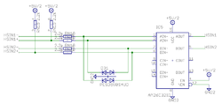
High speed digital input circuity inside the drive. Total 1 of these circuits.
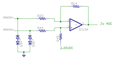
Analog input circuity inside the drive. Total 2 of these circuits.
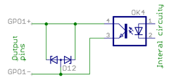
Digital output circuity inside the drive. Total 4 of these circuits.
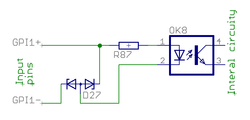
Digital input circuity inside the drive. D27 protects optocoupler from reverse polarity and ESD. Total 4 of these circuits.


Pin-out[edit | edit source]
| Pin # | Pin name | Electrical | Isolated | Function¹ |
|---|---|---|---|---|
| 1 | GND | Supply | No² | Ground |
| 2 | +5V_OUT | Supply | 5V output | |
| 3 | HSIN1- | High speed digital input |
| |
| 4 | HSIN1+ | High speed digital input | ||
| 5 | HSIN2- | High speed digital input |
| |
| 6 | HSIN2+ | High speed digital input | ||
| 7 | ANAIN1- | Analog input | Analog input setpoint | |
| 8 | ANAIN1+ | Analog input | ||
| 9 | ANAIN2- | Analog input | Direction reversal signal for analog input setpoint signal. | |
| 10 | ANAIN2+ | Analog input | ||
| 11 | GPO1- | Digital output | Yes² | Servo ready status. True when drive is initialized and ready to accept user commands/setpoint. |
| 12 | GPO1+ | Digital output | ||
| 13 | GPO2- | Digital output | Position/velocity control mode tracking error warning status. True when tracking error has reached more than user configured 1/8 of fault limit value or when drive is not enabled. May be used by controller to throttle the setpoint thus avoid triggering an tracking error fault. May require FW upgrade. | |
| 14 | GPO2+ | Digital output | ||
| 15 | GPO3- | Digital output | Fault stop status. True when drive is stopped due to fault. | |
| 16 | GPO3+ | Digital output | ||
| 17 | GPO4- | Digital output | Braking status. Set true when drive attempts to brake motor. | |
| 18 | GPO4+ | Digital output | ||
| 19 | GPI1- | Digital input | Home switch input. | |
| 20 | GPI1+ | Digital input | ||
| 21 | GPI2- | Digital input | Positive feed enable input. Used for axis limit switches. | |
| 22 | GPI2+ | Digital input | ||
| 23 | GPI3- | Digital input | Negative feed enable input. Used for axis limit switches. | |
| 24 | GPI3+ | Digital input | ||
| 25 | GPI4- | Digital input | Clear drive faults input. Transition from false to true attempts to reset active faults of drive. If drive is simultaneously in enabled state, motor will start moving immediately. | |
| 26 | GPI4+ | Digital input |
¹) This is the default function with stock firmware. Function may be different in future or custom firmware versions.
²) Non-isolated lines are referenced to GND pin / J3 V- terminal. Isolated lines have functional isolation between GND and other isolated +-/- pairs.
Wiring guide[edit | edit source]
Supply[edit | edit source]
Supply pins output a regulated 5V voltage to external circuits. GND pin is tied to J3 connector V- terminal.
- Electrical properties
- Output voltage 4.9-5.2 V
- Maximum load 500 mA
- Maximum injected current -10 mA
| Never connect multiple supply outputs parallel. Supply output may be connected only current consuming circuity to prevent current injection to the supply port. |
High speed digital input group[edit | edit source]
HSIN is differential digital input capable of receiving digital signals up to 4 MHz.
Electrical properties
- Maximum voltage to HSINx+/- pins referenced to GND: -0.5 to 6V. Nominal 3.3 or 5.0V.
- Maximum injected current +/- 10 mA
- When negative input (HSINx-) is left floating, it floats around 2.5V
- Input state reads logic 1 when voltage on positive pin is greater than voltage on negative pin, otherwise it's logic 0
Wiring when driving using differential source
- Positive outputs of source to HSINx+
- Negative outputs of source to HSINx-
- GND must be connected to source ground
Wiring when driving using single ended source (TTL, CMOS or open collector)
- Outputs of source to HSINx+
- Leave HSINx- floating
- GND must be connected to source ground
Analog input group[edit | edit source]
Analog input accepts ±10V from and may be used as setpoint signal. Electrical properties
- Input impedance ~10 kΩ
- Maximum ANAINx+/- pin voltage vs GND ±25V
- Maximum injected current ±10 mA
- Sampling resolution 12 bits
Wiring to differential signal source
- Connect positive output to ANAINx+
- Connect negative (inverted) output to ANAINx-
- Connect source ground to GND
Wiring to single ended signal source
- Connect output to ANAINx+
- Connect source ground to ANAINx-
- Connect source ground to GND
Wiring to 0-10V analog output with digital direction output:
- Follow the earlier guidelines but connect controller's direction signal to ANAIN2+ and the ground reference of digital output to ANAIN2-. Setpoint gets inverted inside the drive if ANAIN2 voltage is between 3-24VDC and non-inverted between 0-3VDC. May require FW upgrade.
Digital output group[edit | edit source]
Digital output is an optoisolated transistor output to drive various types of inputs of target devices (logic gates, relays, lights etc) Electrical properties
- Load voltage range 3-24V
- Maximum allowed load 50 mA
- Logic 1 state equals conducting state of optocoupler transistor (current flows from GPO+ to GPO- pins), logic 0 stops current flow between GPO+ to GPO- pins.
- + to - pin voltage drop at 50 mA less than 2 VDC
Wiring to logic gate input (CMOS or TTL)
- Connect GPO+ pin to target VCC (typ 5V)
- Connect GPO- pin to target input pin (so input pin is pulled to 5V when output state is logic 1)
| Multiple GPO's may be wired parallel to combine multiple status signals into one wire. In such connection the combined output becomes logic 1 (conductive) if any of the paralleled outputs becomes logic 1. |
Digital input group[edit | edit source]

Digital inputs are optoisolated (floating potential) inputs for general purpose control signals. Electrical properties
- Signal voltage range 3-24V
- Logic 0 when difference between +/- inputs less than 1.5V, logic 1 when voltage is between 2.9-25V
- Current needed to drive logic 1 is 0.8-9 mA depending on input voltage
- Maximum voltage difference between GPIx+/- inputs 27 VDC
- Maximum voltage difference between GPIx+/- inputs vs GND 120 VDC
Connection to electromechanical switch or relay
- See schematics image in right side
Connection to CMOS source
- Connect source output to GPIx+ input
- Connect source ground to GPIx- input
Connection to open collector or TTL source
- Connect source output to GPIx- input
- Connect source VCC (typ 5V) to GPOx+ input
| Digital input and output isolation is only functional and does not provide safety insulation. Connect only to ELV circuits. |
Examples[edit | edit source]
Wiring axis limit and home switches to J5[edit | edit source]
To operate the motor, limit switches must be connected to the GPI1 and GPI2. Feeding logic 1 to one of these ports enables axis motion feed in certain direction.
The behavior of feed enable signals can be configured via Granity machine tab. Logic 1 to these pins is required for drive operation:
- GPI1 - enable positive direction feed.
- GPI2 - enable negative direction feed.
Home switch (optional):
- GPI3 - home switch input. Polarity can be configured via Granity.
In the image below A way to connect switches to J5 port. Inputs are supplied by the J5 connector 5V output. Alternatively the switches may be also supplied from an external 5-24VDC supply.

The example below illustrates an alternative way of connecting limit switches that are connected in series. However this way requires that axis is being manually pulled away from end of travel if either switch is open as drive doesn't know which way is the safe running direction.

Alternative limit switch wiring considerations[edit | edit source]
It is possible to connect limit switches several way, or omit them completely. The table below summarizes the different methods:
| Method # | Connections / configurations | End of travel causes a fault stop state | End of travel causes active braking of motor | Can move motor electrically out end of travel | Remarks |
|---|---|---|---|---|---|
| A | Connect limit switches independently to GPI2 and GPI3 inputs | Yes (but depends on parameterization) | Yes (but depends on parameterization) | Yes | This is the most typical method used |
| B | Connect limit switches in series to GPI2 and GPI3 inputs parallel | Yes (but depends on parameterization) | Yes (but depends on parameterization) | No | Drive has info only that limit switch is open but no info about which way is safe to move |
| C | No limit switches, instead use homing function (position control mode only) and set soft travel limits by parameterization | No | Yes | Yes | Sensorless & wireless solution |
| D | Connect limit switches Safe torque off input | Yes | No, motor may free wheel | No | A very secure way to remove torque from motor. If such feature is desired, it's recommended to install second pair of limit switches or use soft travel limits that stop motion before the STO switches, so STO switches would serve only as backup. |
| E | Connect limit switch to enable drive input | No | Yes | Yes |
Pulse and direction setpoint[edit | edit source]
This example shows how to wire a typical single ended pulse and direction controller.

Quadrature signal setpoint[edit | edit source]
This example shows how to wire a typical single ended quadrature controller.

PWM signal setpoing[edit | edit source]
This example shows how to wire a typical single ended PWM controller.

Analog signal setpoint[edit | edit source]
This example shows how to wire a typical single ended Analog setpoint controller. Maximum analog signal voltage is +/-10V.

0-10V analog input with digital direction signal[edit | edit source]
Follow the earlier guidelines but connect controller's direction signal to ANAIN2+ and the ground reference of digital output to ANAIN2-. Setpoint gets inverted inside the drive if ANAIN2 voltage is between 3-24VDC and non-inverted between 0-3VDC. May require FW upgrade.
Complete example with pulse & direction[edit | edit source]
The examples above can be combined to achieve the user goals. The example below has complete set of I/O features used.
- Pulse & direction set point
- Clear faults output (off-on-off pulse generated by controller user if FAULT input goes on)
- Monitoring of drive state: servo ready, tracking error warning, drive fault, motor braking status
- Axis limit switches & home switch
Notes:
- The controller in the example has 5 volt single ended inputs & outputs
- Controller inputs have pull-down resistor or other means to ensure off or 0 state when input is floating
- It's not required to to monitor & control the I/O lines at controller

Complete example with differential analog setpoint[edit | edit source]
Same as above expect this time the setpoint signal is a differential analog voltage output (max +/-10V).

Braking resistor[edit | edit source]
Regenerative resistors are usually a part with servo systems to absorb returned energy from decelerating or braking servo axis.
Servo drive with motor can act two ways: energy supply and energy generator. The generator behavior occurs during decelerations and this causes current flow from motor to drive power supply capacitors. If that generated energy is not absorbed anywhere, the voltage of capacitors will rise above overvoltage threshold and trigger an software clearable overvoltage fault.
| In most installations braking resistor is not needed at all. Resistor is needed in cases where fast moving motor with high inertial load is stopped rapidly causing conversion of the kinetic energy into electric current which needs to be dissipated by a resistor. Experimenting without resistor is safe as drive's overvoltage protection will prevent any damage occurring. If drive faults to overvoltage fault during deceleration, then try adjusting Over voltage fault thresholdFOV to higher value or add a braking resistor. |
Overvoltage faults[edit | edit source]
Scenarios where returned energy is causing the rise of HV DC bus voltage:
- Deceleration of motor speed when there is significant amount of energy stored in mechanical motion (rotating inertia or moving mass). This typically occurs with spindles and linear axes.
- Sudden reversal of torque setpoint. This can generate voltage spike even when motor is standing still. This typically occurs in high bandwidth torque control applications (such as Force feedback system (FFB)). These spikes are very short and an added capacitor to HV DC bus and/or low resistance regenerative resistor can provide a solution.
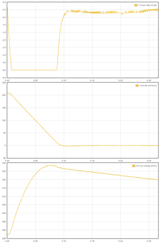
Voltage generation during deceleration of motor (motor current is negative, current is pumped to HV DC bus causing a 40 VDC rise).
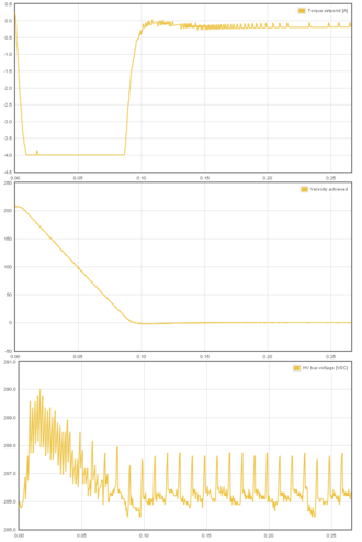
Voltage generation during deceleration of motor (motor current is negative, current is pumped to HV DC bus). However, in this case drive is equipped with regenerative resistor and tightly set Over voltage fault thresholdFOV parameter which prevents the significant voltage rise (only 5 VDC rise).
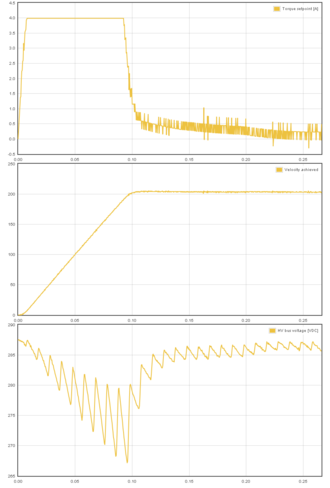
Example of accelerating motor (motor current is positive, power is drawn from HV DC bus which is causing a temporary voltage drop). Rectified 50 Hz mains AC ripple is easily seen in the voltage graph.


See also[edit | edit source]
- Overvoltage and undervoltage faults - practical guide for sizing regenerative resistor
Argon supports connecting braking resistor directly to drive J4 connector.
Suitable resistor type[edit | edit source]
Characteristics of Argon regenerative resistor output:
| Property | Value | Units |
|---|---|---|
| Maximum current | 6 | A |
| Series fuse | 8 | A |
| Minimum allowed resistance @ 230 VAC supply | 63 | Ω |
| Minimum allowed resistance @ 115 VAC supply | 35 | Ω |
| Resistor power dissipation | 0-2400¹ | W |
¹) Power dissipation depends on how much system's kinetic energy is directed to the resistor
Recommended resistor specifications:
- Resistance 80-100 ohms @ 220-240 VAC
- Resistance 40-50 ohms @ 110-120 VAC
- Power rating 150-300 Watts, this may greatly vary depending on how much energy the braking resistor must absorb
- Wire wound construction (no film resistors unless high peak energy capable)
- Preferrable in metal housing for grounding/noise shielding
The 250W resistor in the image can absorb enough peak energy to stop 100 kg mechanical linear axis moving up to 3 m/s.
Example of suitable resistor for most 220-240 VAC installations: Tyco HSC 250 82R (data sheet pdf).
Installation[edit | edit source]

The image aside shows proper wiring of braking resistor. Proper installation has:
- Shielded cable with 3 conductors with wire gauge at least 0.75 mm² / 18 AWG
- Cable shield AND earth conductor connected to drive PE terminal
- Earth conductor connected to resistor casing. Place toothed locking washers between wire terminal and resistor to break the insulating coating of resistor case.
- Two other conductors connected to resistor terminals through 8A fast blow fuse
- Resistor should be also mounted on heat sink
- Additionally it is a recommended to shield the resistor terminals from accidental touching
Parameterization[edit | edit source]
The important parameter that controls usage of resistor in Granity is the over voltage level Over voltage fault thresholdFOV. Drive starts conducting current through resistor when HV DC bus voltage is near FOV value. It is important to set FOV high enough to prevent drive from using resistor constantly while AC supply is connected to the drive. The formula for mimimum FOV value is: FOVminimum=VAC*1.6. I.e. on nominal 230 VAC bus the FOV value should be set to no less than 368 VDC.
| Setting Over voltage fault thresholdFOV value too low causes drive to use resistor constantly thus causing constant heating of resistor. Resistor easily overheats and burns in such case. After setting FOV, monitor resistor temperature for a minute in normal use to ensure that it is not over heating. |
Resistor sharing[edit | edit source]
It is possible to share HV DC link between Argon drives to reduce number of braking resistors needed. Sharing DC bus also forms a higher power HV DC supply between the drives allowing higher power drawn from a single drive if other drives are running on lighter load.

| The terminals of the resistors are connected to dangerous voltages. Never touch them before drive power has been safely discharged. |
Parameterization[edit | edit source]
Warning: Display title "Argon parameterization" overrides earlier display title "Argon J5 connector wiring".This article will describe how to set-up Argon parameters with Granity to make motor operational and ready for servo tuning.
Preparations and connection[edit | edit source]
As the goal is to parameterize and make motor operational, we should have:
- The drive and motor fully wired. However it's not required to have controller (to J5 port) or braking resistor connected at this point.
- Be familiar with the operation and parameters of Granity. Make sure you have read Granity user guide.
- Granity connection working. See Making the first Granity connection
Walk-through of initial parameterization[edit | edit source]
In this chapter we walk-trough all Granity tabs and modify the parameter needed. This guide assumes that the drive is in factory defaults state (not configured before). Restore drive to factory state can be done by uploading a firmware file to the drive.
| Experimenting with drive parameters is (mostly) safe. If motor is attached to machine or bench for testing and nothing is attached to shaft (so motor can't jump but it can spin freely), then playing with all drive parameters can be regarded safe. The most important parameters are proper motor Peak current limitMMC and Continuous current limitMCC to avoid overheating of motor. If unsure of proper current limits, start with low values and increase gradually if motor stays cool. |
Connect tab[edit | edit source]
No other actions than connect to drive needed on this tab. Once connection successful, proceed to the next tab.
Goals tab[edit | edit source]
The factory defaults (torque control as control mode and serial only as setpoint) as well as the other defaults are the correct ones for beginning.
Machine tab[edit | edit source]
In this tab we configure the motor and its feedback device.
Axis mechanics[edit | edit source]
Parameters Axis type & unitsAXT and Axis scaleAXS affect only on the unit conversion of Granity parameters (such as acceleration/velocity limit unit conversions) and has no effect on drive operation.
Choose your axis type and scale, or leave them as defaults.
Motor[edit | edit source]
Find motor parameters from the motor data sheet/manufacturer specifications.
- Choose motor type from the drown down list Motor typeMT. If motor is linear type, see configuring linear servo motor.
- Set motor Pole countMPC (non-brush DC motors only). If unsure, see Determining motor pole count.
- Set Maximum speedMMS of the motor, or alternatively the maximum allowed motor speed in the target application
- Set motor Peak current limitMMC and Peak current limitMMC current values. If non-brush DC motor type has been selected, then these are measured as the peak value of sine. See Motor peak and continuous current limits for description.
- Set motor Coil resistanceMR and Coil inductanceML, these values are measured Phase-to-phase. If unavailable, perform Tuning torque controller manually after initial parameters are set.
- Set Thermal time constantMTC. Motor thermal time constant value in seconds, used for thermal modeling of motor to avoid motor overheating with Peak current limitMMC. If not available, use formula 200*motor_weight (kg) as approximate, so a 2 kg motor would get a 400 second time constant. There is no guarantee of accuracy of this method.
| As torque is directly proportional to motor current, it is advisable to set current limits lower at the beginning of testing. I.e. 50% of motor's rated current will produce 50% of motor's rated torque. |
Feedback device[edit | edit source]
- Choose feedback device type from the drop down Feedback deviceFBD
- Set feedback device resolution. If Feedback deviceFBD is quadrature encoder, then manufacturers typically give resolution as pulses per revolution (PPR) or lines per revolution (LPR) which are the same thing and shall be entered directly into Feedback device resolutionFBR field. Some manufactures also call PPR as CPR.
- Configure the polarity of feedback device counting direction by Invert feedback directionFBI parameter. Motor and feedback device must have same electrical positive rotation direction to make a stable servo system. If your system shows no stability (instant following error after a motor "jump"), try changing this setting.
- Leave the Hall sensors Off from the parameter Hall sensorsFBH during initial setup. Enable later if necessary (see when).
- For SinCos encoders, see Using_SinCos_encoder.
Tuning[edit | edit source]
Tuning tab contains feedback gain values for velocity and position control modes as well as torque bandwidth limit setting. Configuring these parameters are documented in Servo motor tuning guide. However, before proceeding into tuning, go through all other settings listed in this article.
Fault limits[edit | edit source]
Fault limits define the conditions in which drive is willing to operate. If condition is out of the set values, drive will enter into a fault state and stop motor control until errors are cleared.
Drive fault limits[edit | edit source]
These settings specify drive electrical condition such as supply voltage and over current tolerance.
- Leave Over current toleranceFOC value as default if no overcurrent faults occur. See Tuning torque controller if overcurrent faults occur.
- Set Under voltage fault thresholdFUV and Over voltage fault thresholdFOV by following the page Configuring drive voltage limits FUV and FOV.
- It is important to goal deviation faults (i.e. Goal faults filter timeFFT, Position tracking error thresholdFPT, Velocity tracking error thresholdFVT, Over speed faultFEV) as low as possible. Set them so that faults don't occur during normal operation but any anomaly or unexpected behavior will trigger them.
| If goal deviation faults are unnecessary high, drive may pose a danger in case of unexpected behavior. For example if motor starts running away full speed without command, then proper velocity fault threshold values may save from damage. |
Goal deviation faults[edit | edit source]
These faults adjust motor monitoring during operation. Drive will enter into fault state if motor condition deviates more than allowed from the desired condition. See Granity unit conversion before adjusting.
- Goal faults filter timeFFT sets the time how fast Position tracking error thresholdFPT, Velocity tracking error thresholdFVT, Over speed faultFEV and Motion fault thresholdFMO faults react. Setting higher time value allows drive to continue operation over short deviations thus avoid false triggering. Set this from 0.0 to 0.2 seconds in the beginning.
- Set Position tracking error threshold Position tracking error thresholdFPT according how much mechanical axis is allowed to deviate from the setpoint position in position control mode.
- Set Velocity tracking error threshold Velocity tracking error thresholdFVT according how much motor or axis speed may may deviate from the velocity setpoint. This affects also in position mode as velocity controller is the intermediate step between torque and position controllers.
- Set Over speed faultFEV according to the maximum speed allowed for the motor or axis. Helps to stop motor if system goes totally out of control and speeds up spuriously.
- Leave Motion fault thresholdFMO as 0 (0 = disabled) for the beginning. Using nonzero value enables motion fault.
- Choose Limit switch functionLFS according to your preference. If other than Do nothing option requires that limit switches are installed and connected to J5 port. Note: at the moment Servo stop option is active in the drive firmware and will do nothing until FW upgrade enables it.
Testing tab[edit | edit source]
These settings does not affect drive operation, so nothing to be changed here at this point. These controls will be used for servo tuning purposes and fault analysis.
Servo motor tuning[edit | edit source]
Tuning a servo motor is a compulsory task to make motor behave as desired and perform well during operation. Follow the Servo motor tuning guide.
Finishing touches[edit | edit source]
The last step of parameterization is to adapt settings to match the motion controller. Steps:
- Choose setpoint input Setpoint inputCRI to match your motion controller.
- If external motion controller with acceleration limit (such as CNC controller) is being used, then it is advised to set Acceleration limitCAL value to maximum of 32767 (unlimited acceleration) after motor tuning to enable motion tracking without delay. Use a limited acceleration value if drive is being used with pulse burst positioning or SimpleMotion V2 controller.
- If setpoint is too sensitive or not sensitive enough (such as limiting speed), then adjust setpoint scaling factory by adjusting Setpoint multiplierMUL and Setpoint dividerDIV.
- If setpoint signal is noisy or jittering, try enabling Setpoint smoothingCIS to smoothen it inside drive. However, leave Setpoint smoothingCIS disabled if setpoint tracking without any delay is desired.
- Set-up homing if required by application
Servo tuning basics[edit | edit source]
Driving a servo motor is much like driving a car. Driving a car has many similarities including the key concepts of torque, velocity and position control. Most of this happens in the driver's head the same way than a servo drive does with a motor.
For those who are already familiar with the basics, see the principles of real world servo motor drive from article Signal path of motor drive.
Driving (a.k.a servoing) a car[edit | edit source]
Driving a car to a destination is much like driving a servo motor to it's destination position. The analogies in between are:
| Car | Servo axis |
|---|---|
| Pedal (motor gasoline feed) | Torque setpoint (motor current feed) |
| Speed limit | Velocity setpoint |
| Target location | Position setpoint |
| Speed meter | Velocity feedback |
| Trip meter | Position feedback |
| Car driver | Servo drive |

The ultimate goal of driver is to get to the target. To achieve this, he follows the road (trajectory) at certain velocity and decelerates once target is being reached. Without knowing, the driver acts as servo controller where he:
- Controls car's velocity based on the speed meter value and speed limit
- Controls car's position based on trip meter's reading or by observing location trough the windshield
- All actions the driver makes, is based on comparing the setpoints and the actual state
Servo controller basics[edit | edit source]
Controller gains and a PI controller[edit | edit source]
Controller gain means sensitivity to change output due to tracking error (the difference between setpoint and feedback).
The simplest form of feedback based controller is a proportional gain controller (P controller) where output follows the formula output = Pgain*(setpoint-feedback). The problem of proportional gain controller is that it may never reach the setpoint because output starts approaching zero when the following error is reaching zero.
Because of this, it's better to add in integrating component to the controller (forming PI controller). Integrator accumulates the tracking error to a integrator variable. Integrator variable is like a bucket of water, when you add water, the water level rises and when you take out water, the level lowers. In controller the equation becomes: output = Pgain*(setpoint-feedback) + Igain*IntegralOf(setpoint-feedback).
The characteristics of feedback gain variables:
- P-gain - reacts instantly to the tracking error but can't eliminate tracking error completely
- I-gain - reacts slowly over time, adjusts output until tracking error is zero
When driving a car, human brain closely resembles the operation of a PI controller. For in-depth info about PI controllers and its variants, see the Wikipedia article PID controller.
Tuning the gains[edit | edit source]
Controller tuning means finding of the optimum gain values for the given system.
The proper gain values always depend on many aspects, especially the target system dynamic properties (such as motor properties, axis transmission ratios, inertias and masses). Change of properties introduces the requirement of tuning the gain values as gain values that work fine in one system may not behave satisfactory on a different system.
In servo drive case, this means that each motor type and mechanical axis need to be tuned separately. However, if axis and motors are identical, then the same gains should work equally.
Gain tuning (car) example[edit | edit source]
The following series of images illustrate an imaginary car driving scenario where the driver acts as velocity controller of the car. The magnitude of PI gain values equal the driver's aggressivity of controlling the pedal to reach the desired speed.
Low gains - sluggish response[edit | edit source]

If the gains are set too low, the system response tends to be sluggish and sometimes leave a static tracking error (not reaching setpoint in any time). In this imaginary case we could think PI gains to be P=20 I=10.
Too high gains - oscillation & instability[edit | edit source]

If the gains are set too high, the system becomes overshooting, oscillating and less stable. Here the comparable PI gains could be P=200 I=100
Optimum gains - only little overshoot[edit | edit source]

When the gains are tuned correctly, the response shows rapid response with low overshoot and no ringing or oscillations. The comparable gains here P=50 I=25.
Optimum gains with realistic setpoint - optimum response[edit | edit source]

The response can be improved further by introducing a limit to the slew rate of setpoint signal. The controller behaves optimally when the system is able to follow the setpoint continuously with little tracking error. In this case the gains could be same as before, P=50 I=25.
Real servo motor controller[edit | edit source]
See the principles of real world servo motor drive from article Signal path of motor drive.
| Read next |
Tuning torque controller[edit | edit source]
Torque controller tuning means finding the correct gain values for a torque controller inside the servo drive to achieve a proper response from a torque setpoint change.
| Torque controller inside drive is implemented by a PI controller where P and I gains are controlled proportionally by Coil inductanceML and Coil resistanceMR respectively. |
Direct inductance & resistance setting method[edit | edit source]
In Granity, there is no dedicated torque control PI gains as the software supports entering motor coil inductance and resistance where the suitable PI gains are calculated from.
Method 1 (preferred)[edit | edit source]
If you are using a drive model that supports automatic measurement of inductance and resistance, follow the instructions here.
Method 2[edit | edit source]
If the above measurement function is not available, and your motor comes with coil specifications containing phase-to-phase inductance and resistance values, then the only necessary step is to enter the given values into motor Coil resistanceMR and Coil inductanceML parameter fields. In case of troubles with this method, proceed with manual tuning method.
Manual tuning method[edit | edit source]
Manual tuning of torque controller is some times done in order to optimize the torque controller response or to find the correct motor Coil resistanceMR and Coil inductanceML parameters if unknown. Manual tuning also usually yields better torque response than the direct method which may help tuning of velocity or position tuning.
| If satisfactory performance was achieved by direct inductance & resistance setting method, you may skip the manual tuning method. |
In order to change torque tuning, one needs to change motor Coil resistanceMR and Coil inductanceML parameters until the torque response looks satisfactory.
Preparations[edit | edit source]

Steps to do to begin torque tuning:
- Ensure that motor is parameterized correctly and working
- Fix the motor shaft so that it cannot rotate under full peak torque of the motor
- Make following parameter changes to Granity and click apply afterwards:
- Set drive in torque control mode Control modeCM
- Set Torque bandwidth limitTBW to maximum
- Choose Serial only setpoint input Control modeCM
- Untick Setpoint smoothingCIS
- Set Goals tab Setpoint dividerDIV and Setpoint multiplierMUL to 50
- Make other necessary adjustments to have drive powered and enabled
- Set-up the test stimulus and capture settings from Testing tab:
- Set target setpoint 1 TSP1 to 2000-15000 (see the chapter below for finding the optimum test setpoint)
- Set delay 1 TSD1 to 0.05 seconds
- Set target setpoint 2 TSP2 to 0
- Set delay1 TSD2 to 0.5 s
- Choose sample rate Sample rateTSR of 10000 Hz or more
- Choose Capture setpoint change ind positive direction from the dropdown
- Tick Continuously repeating capture
- Tick Torque setpoint and Torque achieved from signals
- Tick Start capture to begin continous capture.
- Tick Enable test stimulusTSE to begin a pulsed torque generation
Once the steps above are done, motor should be generating short torque pulses to a fixed shaft and torque response graphs should appear on the right side of Granity about once in 3-5 seconds.
Finding optimium test current (TSP1)[edit | edit source]
To find optimum value for TSP1, enable capture channel called "Motor output voltage" to see how much voltage is driven to motor during rising the edge of torque. For optimum TSP1 value the voltage peak should lie within 20% to 80%. If voltage gets saturated (100%), reduce TSP1 value until it stays below 80%. Images below illustrate the wrong case (first image) and correctly set case (second image).
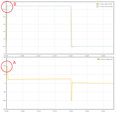
TSP1 value too high causing output voltage saturation to 100% (A). This will cause torque tuning to look better than it actually is (B).
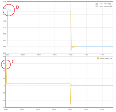
TSP1 value set optimally and peak voltage stays at 60% (C). Now the test reveals that present settings are causing some torque overshooting (D) and we can eliminate it by adjusting ML and MR values.


Adjusting MR and ML to for optimum torque control[edit | edit source]
The task here is to adjust the Coil resistanceMR and Coil inductanceML parameters to achieve near optimum step response for the torque controller. Observe the images below for guidance.
| If the drive faults during this testing due to overcurrent, try reducing TSP1 value or increase Over current toleranceFOC parameter. Or try radically different Coil resistanceMR and Coil inductanceML values. |

In this case the Coil resistanceMR value has been set too low causing slowly rising achieved torque curve. Such slow response would reduce servo responsiveness.

In the opposite case (too high Coil resistanceMR value) the response shows wavy oscillations and ovesrhoot.

Same kind of phenomenon will be seen if motor Coil inductanceML value is too low. Finding oscillation free tuning is finding the correct balance between the MR and ML as both affect each other.

Too high Coil inductanceML will cause sharp overshooting and high frequency oscillations. Motor may produce audible noise if oscillations are continuous (occurs with way too high ML).

The above image shows near optimum torque response with fast rising edge combined to minimal overshoot.

The above image shows what may happen if motor shaft is not fixed properly (allowed to rotate). This is with the same optimum settings like the previous image.
Steps to do after manual tuning finished[edit | edit source]
- Stop test stimulus by unticking Enable test stimulusTSE
- Stop scope catpure by unticking Continuously repeating capture
- Undo all temporary changes made to settings (such as Torque bandwidth limitTBW, Control modeCM, Setpoint dividerDIV, Setpoint multiplierMUL) but leave the optimized Coil resistanceMR and Coil inductanceML values active
- Save settings to drive memory by clicking Save settings on drive non-volatile memory button
Using drive in torque mode[edit | edit source]
If torque mode is the final desired operating mode, set-up the setpoint signal source from Granity Goals tab. Also see Signal path of motor drive for explanation of torque setpoint scale.
Read next
|
Tuning velocity controller[edit | edit source]
Velocity controller tuning means finding the correct drive settings and feedback gain values to achieve a proper Servo stiffness and response to a velocity setpoint change.
This tuning guide is for you if the final application uses the motor in velocity control mode such as spindle or as position mode with external closed loop position controller such as LinuxCNC.
Velocity control tuning method[edit | edit source]
| If motor has been tuned without the real load (i.e. motor shaft not attached), tuning parameters should be re-adjusted with the real load as the dynamic properties of the load has a significant effect on them. Large change of load properties may even cause servo instability. |
Preparations[edit | edit source]


Steps to do to begin position tuning:
- Ensure that motor is parameterized correctly and working and torque control tuning has been properly done.
- Attach motor to the target load and ensure it can rotate in both directions infinitely
- Make following parameter changes to Granity and click apply afterwards:
- Set drive in velocity control mode Control modeCM
- Choose Serial only setpoint input Control modeCM
- Make other necessary adjustments to have drive powered and enabled
- Untick Setpoint smoothingCIS
- Set Goals tab Setpoint dividerDIV and Setpoint multiplierMUL to 50
- Set Acceleration limitCAL & Velocity limitCVL reasonably to the levels that motor is expected to handle
- Set-up the test stimulus and capture settings from Testing tab (an example, may be varied):
- Set target setpoint 1 TSP1 between 1000 and 16383 (16383 equals the max speed that is configured via Velocity limitCVL)
- Set delay 1 TSD1 to 0.25 seconds
- Set target setpoint 2 TSP2 to same, but negative, value of TSP1
- Set delay1 STD2 to 0.25 s
- Choose Sample rateTSR of 500 to 2500 Hz
- Choose Capture setpoint change in positive direction from the dropdown
- Tick Continuously repeating capture
- Tick Velocity setpoint and Velocity achieved from signals
- Tick Start capture to begin continous capture.
- Tick Enable test stimulusTSE to begin a continuous position back and forth spinning motion generation
Once the steps above are done, motor should be generating direction reversing spinning and velocity response graphs should appear on the right side of Granity about once in 3-5 seconds.
Finding velocity control gain values[edit | edit source]
| If the drive faults during this testing due to overcurrent, see Tuning torque controller for solutions. If drive faults due to following error or motion fault, increase the goal deviation fault limits at Fault limits tab. |
Tuning protocol[edit | edit source]
Tuning is begun with low or medium target speeds (TSP1 & 2 values below 5000).

Initial velocity response with the default settings. As seen from the achieved velocity graph, it follows the setpoint velocity lazily and exhibits overshooting. In such state motor servo stiffness is low can be easily decelerated by adding load to the shaft.

Begin tuning by increasing Velocity P gainKVP. This makes motor follow velocity setpoint much better.
To try different gains, go to Tuning tab, change value and click the Apply settings button.

When Velocity P gainKVP has been increased too much, the system becomes unstable and may start oscillating. In such case, you may hit Esc button to disable drive, reduce the gain and enable drive again.
Tip: torque bandwidth has significant effect on the behavior of KVP value and the point where it goes unstable. One may experiment different Torque bandwidth limitTBW settings to find the optimum.

Once a maximum perfectly stable Velocity P gainKVP value has been found, start increasing Velocity I gainKVI gain by a similar fashion. The higher KVI value is, the better servo stiffness.

If Velocity P gainKVP is increased too much, the result is overshooting and even sustained oscillation. The cure is similar to the too high Velocity P gainKVP as described earlier.

Once stable and stiff gains has been found, increase setpoint values (TSP1 & 2) to test the settings with higher speeds. If necessary adjust the gains experimentally to find the optimum tuning that works satisfactory on all needed speeds.
Advanced tuning: Feed-forwards[edit | edit source]
Feed-forward parameters may be used to boost motor responsiveness to setpoint change. Velocity feed-forward gainVFF and Acceleration feed-forward gainAFF essentially compensate system friction and mass limiting the dynamic performance.
The recommended way to tune FF gains, is to start increasing Velocity feed-forward gainVFF until the optimum level has been found. After that, increase Acceleration feed-forward gainAFF until the optimum point has been reached.

In the image above a sharp response has been achieved even with low feedback gains as feed-forward gains help motor to accelerate as demanded.

The image above shows similar response without feed-forwards but using high feedback gain values (optimally tuned according to the previous chapter).
Problem cases[edit | edit source]
Current/torque saturation[edit | edit source]
In the following test we run motor with higher speeds (TSPn > 10000) to illustrate a typical problem case.

The image above shows acceleration limited by insufficient torque produced by the motor. In this example the acceleration limit is set too high to be accelerated with the given motor torque limits (or current limits).
To verify if the problem happens due to torque limit, tick also Torque achieved and Torque setpoint signals from the Testing tab settings. In such way also motor currents will be displayed simultaneously with the position response curves. If the torque curve is limited to the set Peak current limitMMC, then the problem is insufficient torque. In the image above we can see that the torque curves are saturated/clipping at 5A and -5A levels which matches the configured Peak current limitMMC value of 5A in this demonstration.
To help this, try:
- Increasing current limits Peak current limitMMC and Continuous current limitMCC if possible
- Reducing Acceleration limitCAL and/or Velocity limitCVL limits
Oscillation[edit | edit source]

The above example shows instability and oscillation with high speeds even when the system was stable at lower speeds with the same parameters. In such case tune the system again at the most unfavorable conditions and speeds to achieve stability over all required operating conditions.
Low resolution velocity feedback[edit | edit source]

The above example shows another kind of problem: low resolution of velocity graph. This happens if feedback device resolution is low, and/or test velocity setpoint is low. However tuning is still possible. Tune KVP up until you find instability (you can hear it), and then take it down for 30-50% from that. Then adjust KVI up until graph looks best (no overshooting or oscillations). You may do this procedure with several torque bandwidths (TBW param) to see which gives best result.
Steps to do after tuning finished[edit | edit source]
- Stop test stimulus by unticking Enable test stimulusTSE
- Stop scope capture by unticking Continuously repeating capture
- Undo all temporary changes made to settings
- Save settings to drive memory by clicking Save settings on drive non-volatile memory button
- Set preferred setpoint source Setpoint inputCRI, also consider the use of Setpoint smoothingCIS
- If setpoint signal scaling is needed, adjust Setpoint multiplierMUL and Setpoint dividerDIV values
| Important: if drive will be controlled by an external motion controller with acceleration & velocity limits, such as CNC controller programs like Mach3 or LinuxCNC, then its highly recommended to increase acceleration limit Acceleration limitCAL to the maximum value of 32767 to prevent drive's internal acceleration limiter modifying the trajectory. Instead, set acceleration limit from the controller (i.e. settings of CNC software). |
Using drive in velocity control mode[edit | edit source]
If velocity control mode is the final desired operating mode, set-up the setpoint signal source from Granity Goals tab. Also see Signal path of motor drive for explanation of velocity setpoint scale.
Tuning position controller[edit | edit source]
Position controller tuning means finding the correct drive settings and feedback gain values to achieve a proper Servo stiffness and response to a position setpoint change.
Position control tuning method[edit | edit source]
This article describes a practical approach for finding proper drive parameters to achieve a stable and stiff position control.
| If motor has been tuned without the real load (i.e. motor shaft not attached), tuning parameters should be re-adjusted with the real load as the dynamic properties of the load has a significant effect on them. Large change of load properties may even cause servo instability. |
Preparations[edit | edit source]

Steps to do to begin position tuning:
- Ensure that motor is parameterized correctly and working and torque control tuning has been properly done.
- Attach motor to the target machine in a position where it can rotate in both directions
- Make following parameter changes to Granity and click apply afterwards:
- Set drive in position control mode Control modeCM
- Choose Serial only setpoint input Control modeCM
- Make other necessary adjustments to have drive powered and enabled
- Untick Setpoint smoothingCIS
- Set Goals tab Setpoint dividerDIV and Setpoint multiplierMUL to 50
- Set Acceleration limitCAL & Velocity limitCVL limits reasonably to the levels that motor is expected to handle
- Set-up the test stimulus and capture settings from Testing tab (an example, may be varied):
- Set target setpoint 1 TSP1 to 100
- Set delay 1 TSD1 to 0.25 seconds
- Set target setpoint 2 TSP2 to -100
- Set delay1 TSD2 to 0.25 s
- Choose Sample rateTSR of 500 to 2500 Hz
- Choose Capture setpoint change in positive direction from the dropdown
- Tick Continuously repeating capture
- Tick Position setpoint and Position achieved from signals
- Tick Start capture to begin continous capture.
- Tick Enable test stimulusTSE to begin a continuous position back and forth motion generation
Once the steps above are done, motor should be generating short distance back and forth motion motion and position response graphs should appear on the right side of Granity about once in 3-5 seconds.
Finding velocity & position control gain values[edit | edit source]
The task here is to adjust the Coil resistanceMR and Coil inductanceML parameters to achieve near optimum step response for the torque controller. Observe the images below for guidance.
| If the drive faults during this testing due to overcurrent, see Tuning torque controller for solutions. If drive faults due to following error or motion fault, increase the goal deviation fault limits at Fault limits tab. |

The image above represents the initial position step response with low feedback gains. As seen, motor reaction is sluggish, lagging and has overshooting.

The next step is to increase Velocity P gainKVP gain as much as possible. The graph may start looking acceptable but it motor still has low stiffness thus it will get lag once mechanical load increases.
To try different gains, go to Tuning tab, change value and click the Apply settings button.

When Velocity P gainKVP has been increased too much, the system becomes unstable and may start oscillating. In such case, you may hit Esc button to disable drive, reduce the gain and enable drive again.
Tip: torque bandwidth has significant effect on the behavior of KVP value and the point where it goes unstable. One may experiment different Torque bandwidth limitTBW settings to find the optimum.

Once a maximum perfectly stable Velocity P gainKVP value has been found, start increasing Velocity I gainKVI gain by a similar fashion. The higher KVI value is, the better servo stiffness.

If Velocity P gainKVP is increased too much, the result is instability and oscillation. The cure is similar to the too high Velocity P gainKVP gain as described earlier.

Once both Velocity P gainKVP and Velocity I gainKVI has been optimized, the next step is to increase Position P gainKPP gain the same way. Increasing Position P gainKPP gives better servo stiffness but may also increase overshooting. Overshoot less than 10 feedback device counts is generally considered good.

Finally after playing little bit with all of Velocity P gainKVP, Velocity I gainKVI and Position P gainKPP experimentally, we find a less overshooting response without losing much stiffness.
Curing tracking error and overshoot[edit | edit source]
If servo overshoots too much, or can't follow the trajectory precisely, several cures may be tried.

Reducing Acceleration limitCAL and/or Velocity limitCVL limits makes the trajectory easier to follow and reduces tracking error and overshooting.

The same may be also achieved by utilizing Feed-forward Velocity feed-forward gainVFF and Acceleration feed-forward gainAFF which essentially compensate system friction and mass limiting the dynamic performance.
The recommended way to tune FF gains, is to start increasing Velocity feed-forward gainVFF until the optimum level has been found. After that, increase Acceleration feed-forward gainAFF until the optimum point has been reached.

If following the tuning procedure does not result in satisfactory tracking performance, the problem may be asking too much from the motor. In the example above the acceleration limit is set too high to be accelerated with the given motor torque limits (or current limits).
To verify if the problem happens due to torque limit, tick also Torque achieved and Torque setpoint signals from the Testing tab settings. In such way also motor currents will be displayed simultaneously with the position response curves. If the torque curve is limited to the set, Peak current limitMMC, then the problem is insufficient torque. In the image above we can see that the torque curves are saturated at 4A and -4A levels which matches the configured Peak current limitMMC value of 4A in this demonstration.
To help this, try:
- Increasing Peak current limitMMC and Continuous current limitMCC if possible
- Reducing Acceleration limitCAL and/or Velocity limitCVL limits
Steps to do after tuning finished[edit | edit source]
- Stop test stimulus by unticking Enable test stimulusTSE
- Stop scope capture by unticking Continuously repeating capture
- Undo all temporary changes made to settings
- Save settings to drive memory by clicking Save settings on drive non-volatile memory button
- Set preferred setpoint source Setpoint inputCRI, also consider the use of Setpoint smoothingCIS
- If setpoint signal scaling is needed, adjust Setpoint multiplierMUL and Setpoint dividerDIV values. See Signal path of motor drive for explanation of velocity setpoint scale.
| If drive will be controlled by an external motion controller with acceleration & velocity limits, such as CNC controller programs like Mach3 or LinuxCNC, then its recommended to increase Acceleration limitCAL to the maximum value of 32767 and disable Setpoint smoothingCIS to prevent drive's internal acceleration limiter modifying the setpoint signal. Using these settings effectively disables the internal acceleration limit and let's external controller to control accelerations. |
LED indicators[edit | edit source]
Warning: Display title "Argon LED indicators" overrides earlier display title "Argon parameterization".Argon has four front panel led indicators which have dedicated indicating tasks:- LD1 SimpleMotion transmit led. Blinks when drive transmits data to bus.
- LD2 SimpleMotion receive led. Blinks when drive receives data from bus.
- LD3 Fault indicator
- LD4 Motor control state indicator
How to read indications[edit | edit source]
- LD1 and LD2, blink very briefly during data transmission. Due to short light pulses, these lights appear dimmer than other leds.
- LD3 and LD4 have programmed blinking sequences. Sequences consists series of short (S) and long (L) light pulses. For example LLS means the led will blink two long flashs and then one short flash. After sequence there will be a pause before the sequence repeats.
- LD3 and LD4 are independent and can show fault and motor state simultaneously. To easier reading sequence, cover one led with a thumb to be able to concentrate to one led.
- LD3 and shows the first fault occurred if multiple fault states are active simultaneously.
List of all LD3 and LD4 sequences[edit | edit source]
To see animated images, view this Wiki page in a web browser with animations enabled.
Faults originated from I/O side of drive[edit | edit source]
Only LD3 is being controlled by these faults.
| Fault reason | LED sequence | LED sequence as text |
|---|---|---|
| Hardware |  |
SLLS |
| Program or memory |  |
SLSL |
| Internal comm error (unable to establish comm) |  |
SLSS |
| Internal comm error (in middle of operation) |  |
SSLL |
| SimpleMotion communication |  |
LSSS |
| Other/unknown |  |
LLSL |
Faults originated from GraniteCore side of drive[edit | edit source]
Only LD3 is being controlled by these faults.
| Fault reason | LED sequence | LED sequence as text |
|---|---|---|
| Hardware |  |
LLSS |
| Progral or memory |  |
LSLL |
| Internal comm error (CRC) |  |
LSL |
| Initialization |  |
LSS |
| Over current |  |
SLL |
| Over temperature |  |
LSLS |
| Over voltage |  |
SLS |
| Following error |  |
LS |
| Under voltage |  |
SL |
| Motion blocked or motor runaway | |
SSL |
| Setpoint range exceeded |  |
LSSL |
| Other/unknown, possibly configuration error such as motor mode Motor typeMT not selected |  |
SSSL |
Motor control states[edit | edit source]
Only LD4 is being controlled by these faults.
| Status | LED sequence | LED sequence as text | Motor output powered |
|---|---|---|---|
| Permanent stop (need device reset) |  |
LLS | No |
| Fault stop (observe LD3 for reason) |  |
Off | Depends on fault |
| Follow error recovery motion |  |
LS | Yes |
| Initializing |  |
SL | Yes |
| Homing |  |
LSS | Yes |
| Run |  |
On | yes |
| Other/uncategorized (not any of above). For details, connect with Granity and see status bits. |  |
LLSS | No |
Argon specifications & accessories[edit | edit source]
This page lists official functional, electrical and physical specifications of the ARGON Servo Drive.| This page contains official specifications of a Granite Devices product. For security reasons contents, this Wiki page is protected thus modifiable by Granite Devices staff only. |
Main functionality[edit | edit source]
| Function | Description |
|---|---|
| Servo motor drive | Closed loop control of various types of servo motors by sinusoidal field oriented control with dead-time distortion correction and high dynamic range torque control.
|
| Control modes |
|
| Setpoint types |
See setpoint signal / reference inputs list
|
| Closed loop | Cascaded control loops (PIV):
|
| Feed-forwards | Feed-forwards working in velocity & position control modes:
|
| Homing | Integrated homing function for position control mode:
|
| Feedback devices | See feedback devices list |
| Safety |
|
| Protections |
|
| Power supply |
Two power supply methods:
|
| Motor output current |
|
| Commissioning |
|
| Compliance | CE (LVD & EMC): EN 61800-5-1:2007 and IEC 61000-6-1:2005 |
Mechanical[edit | edit source]
| Property | Value | Units |
|---|---|---|
| Dimensions (with wall mounting tabs)¹ | 51×197×127 (W×H×D) | mm |
| Dimensions (excluding wall mounting tabs)¹ | 51×177×127 (W×H×D) | mm |
| Weight | 0.88 | kg |
| Case materials | Steel (cover), aluminum (heat sink) | |
| Drawings | |
¹) Wall mounting tabs are fixed part of enclosure
Environment[edit | edit source]
| Property | Value | Units |
|---|---|---|
| Operating temperature | 10-70 | °C |
| Storage temperature | -30-90 | °C |
| Humidity | 0-95 non-condensing | % |
| Power dissipation | 2-100¹ | W |
¹) Power dissipation is output current and input voltage related.
Power supply[edit | edit source]
| Supply2 | Input voltage | Input current typ | Input current max |
|---|---|---|---|
| Logic power | 24 VDC +/- 10% | 0.1 - 0.4 A | 0.5 A |
| Motor power³ | 85 - 264 VAC 50/60 Hz | 0 - 16 A1 | 26 A1 |
| 704 - 380 VDC | 0 - 16 A1 | 26 A1 |
1) Estimating true current or power consumption based on this table may be difficult as current demand typically varies greatly and and almost completely depends on motor load conditions.
2) Both logic and motor supplies are required.
3) Features internal inrush current limiter
4) Possible to use from 45 VDC upwards, however short circuit protection feature is lost below 70 VDC.
Motor output[edit | edit source]
| Property | Value | Units | Remarks |
|---|---|---|---|
| Supported motors | AC, BLDC, DC, Linear | Permanent magnet motors only | |
| Continuous output current | 0-12.5 | A (peak value of sine) | User settable limit |
| Peak output current | 0-18 | A (peak value of sine) | Duration 1 sec, then returned to continuous limit. User settable current limit. |
| Maximum effective motor phase output voltage |
|
| |
| Switching frequency | 17.5 | kHz | |
| Maximum modulation depth | 88 | % | Maximum effective output is 88% of HV DC bus voltage. |
| Torque control bandwidth (typ.) | 1-3.3 | kHz | Motor coil dependent |
| Torque control cycle time | 57.1 | µs | |
| Position & velocity control cycle time | 400 | µs | |
| Power conversion efficiency | 90-95 | % | Under typical conditions |
| Motor inductance range @ 230 VAC | 1.4-25 | mH | |
| Motor inductance range @ 115 VAC | 0.7-25 | mH | |
| Motor power range | 0.05 - 1.5 | kW | |
| AC commutation frequency | 0-400 | Hz |
Regenerative resistor[edit | edit source]
| Property | Value | Units |
|---|---|---|
| Maximum current | 6 | A |
| Series fuse | 8 | A |
| Minimum allowed resistance @ 230 VAC supply | 63 | Ω |
| Minimum allowed resistance @ 115 VAC supply | 35 | Ω |
| Resistor power dissipation | 0-2400¹ | W |
¹) Power dissipation depends on how much system's kinetic energy is directed to the resistor
Feedback devices[edit | edit source]
Status of feedback device support[edit | edit source]
| Feedback device type | Status | Electrical interface |
|---|---|---|
| Quadrature incremental encoder | Standard feature | Differential 3-5.5V (RS422), Single ended 3-5.5V (CMOS,TTL,open collector) |
| Hall sensors | Standard feature | Single ended 3-5.5V (CMOS,TTL,open collector). Differential signals accepted. |
| Analog SinCos encoder | Standard feature | 1 V p-p signal, 16X, 64X or 256X resolution interpolation factor (user selectable)2, max 500 kHz input frequency |
| Resolver/synchro | Supported, with adapter | 10 kHz excitation |
| Serial SSI encoder | Not supported¹ | RS422/RS485 |
| Serial BiSS encoder | Not supported¹ | RS422/RS485 |
| Tachogenerator | Not supported¹ |
1) Supported by hardware. Argon is supported as-is, no new features will be added to it. Custom firmware features are possible with the Argon open source firmware.
2) The final resolution will be 4*line_count*interpolation_factor. I.e. with 1000 lines/electrical cycles per revolution SinCos encoder, the supported resolutions are 64000, 256000 and 1024000 counts per revolution. SinCos encoder can be also used without interpolation (4*line_count resolution).
Quadrature encoder electrical properties[edit | edit source]
| Property | Value | Units | Remarks |
|---|---|---|---|
| Encoder count rate | 0-4 | MHz | After 4x decoding, digitally filtered |
| Supply voltage | 4.8-5.2 | V | Supplied from drive |
| Supply current | 0-500 | mA | Supplied from drive |
SinCos encoder electrical properties[edit | edit source]
| Property | Value | Units | Remarks |
|---|---|---|---|
| Input frequency (16X interpolation) | 0-640 | kHz | |
| Input frequency (64X interpolation) | 0-160 | kHz | |
| Input frequency (256X interpolation) | 0-40 | kHz | |
| Supply voltage | 4.8-5.2 | V | Supplied from drive |
| Supply current | 0-500 | mA | Supplied from drive |
| SinCos signal voltage | 0.8-1.2 | Vp-p |
Setpoint signal / reference inputs[edit | edit source]
| Setpoint signal type | Status | Electrical interface |
|---|---|---|
| Analog | Standard feature |
|
| Pulse and direction | Standard feature | Up to 4 MHz step rate, 5V signaling |
| Quadrature | Standard feature | Up to 4 MHz count rate, 5V signaling |
| PWM | Standard feature |
|
| Serial communication | Standard feature | SimpleMotion V2 real-time serial bus with open source SDK. Connect through RS485 or USB. |
| Stand-alone operation or custom setpoint signal | User implementable | May be implemented in the Argon open source firmware |
| EtherCAT | Planned | Realized with add-on board |
See also:
Inputs / outputs[edit | edit source]
List of I/O's[edit | edit source]
- Isolated digital inputs (4 channels) - used for limit & home switches and clear faults signal ¹
- Isolated digital outputs (4 channels) - used for status indication ¹
- Differential analog inputs (2 channels) - used as Analog setpoint ¹
- Differential digital inputs (2 channels) - used for pulse/direction or second encoder ¹
- Digital inputs (3 channels) - used for safe torque off and drive enable
- Digital output (1 channel) - used for motor solenoid brake
¹) Functions may be altered by modifying the Argon open source firmware
Electrical characteristics[edit | edit source]
For detailed specifications, see I/O electrical interfacing and pinout & wiring.
| Property | Typical value | Maximum rating | Units |
|---|---|---|---|
| Protections (all I/O lines) | overvoltage, ESD, short circuit, reverse polarity | ||
| Isolated digital input (GPIx) logic 1 voltage | 4.5-24 | 25.5 | V |
| Isolated digital input (GPIx) logic 0 voltage | 0-1.3 | V | |
| Isolated digital output (GPOx) voltage | 0-24 | 25.5 | V |
| Isolated digital output (GPOx) current drive capability ¹,² | 5-20 | 40 | mA |
| High speed digital input (HSINx) voltage range | 2.7-5.5 | 6.0 | V |
| Analog input input (ANAINx) voltage range | ±10 | ±25 vs GND | V |
| Analog input input (ANAINx) resolution | 12 | bits | |
| Enable input input logic 1 voltage | 20-24 | 25.5 | V |
| STO input input logic 1 voltage | 20-24 | 25.5 | V |
| Motor brake voltage | 12-24 | 25.5 | V |
| Motor brake load current | 0-0.5 | 0.7 | A |
¹) Actual output drive capability may vary from unit to unit. Minimum guaranteed capability is 5 mA.
²) Do not exceed GPO safe operating area (SOA). Loading GPOx pin is within SOA when following equation is true: Voltage_drop_over_GPOx_pin_pair*Load_current < 0.1W. Example: if voltage over GPOx pins is 5V and current 0.01A, then 5V*0.01A=0.05W which is less than 0.1W so the operation is safe. The recommended practice is to drive only high impedance circuits with GPO to avoid overloading.
Communication[edit | edit source]
| Property | Value | Units |
|---|---|---|
| Communication protocol | SimpleMotion V2 | |
| Default bitrate | 460800 | BPS |
| Maximum number of Argon devices chained in a single bus | 15 | pcs |
| Command throughput | Up to 10000 | Commands/s |
Safety[edit | edit source]
| Feature | Properties | Remarks |
|---|---|---|
| Safe torque off |
|
STO1 safe up to 6 A AC RMS input current. Not operational if AC input > 6 A RMS AC or if DC voltage is being supplied to drive through L & N terminals or VP & VN terminals. |
| Control error detection |
|
|
| Electrical safety |
|
Galvanic isolation on J1, J2, J3 and J5 connectors against J4 with live AC mains voltages |
| Overload safety |
|
Warnings[edit | edit source]
| Exceeding ratings may affect drive operation and cause instability or even damage the drive or other equipment. Damaged equipment may pose danger to users. |
Mating connectors and accessories[edit | edit source]
Warning: Display title "Argon mating connectors and accessories" overrides earlier display title "Argon LED indicators".
This page lists available mating connectors, accessories and spare parts for Argon (servo drive). Most parts or equivalents are available from large number of distributors. Feel free to extend this list.Connectors[edit | edit source]
J1 connector[edit | edit source]
| Description | Manufacturer | Part number | Distributors and order codes |
|---|---|---|---|
| PLUG, D, SOLDER, 15WAY | MULTICOMP | 5501-15PA-02-F1 |
|
Accessories[edit | edit source]
| Description | Manufacturer | Part number | Distributors and order codes |
|---|---|---|---|
| D-SUB BACKSHELL, 15WAY | MH CONNECTORS | DPPK15-GREY-K |
|
J2 connector[edit | edit source]
Cable assemblies[edit | edit source]
Cable used for J2 should be shielded (S/FTP or FTP, not UTP) type.
| Description | Manufacturer | Part number | Distributors and order codes |
|---|---|---|---|
| Premium patch cable 0.5m | VIDEK | 3962-0.5 | Farnell 1525999 |
| Premium patch cable 1m | VIDEK | 3962-1 | |
| Premium patch cable 2m | VIDEK | 3962-2 | Farnell 1525753 |
| Premium patch cable 5m | VIDEK | 3962-5 | Farnell 1525755 |
| Premium patch cable 10m | VIDEK | 3962-10 | |
| Shielded patch cable 0.5m | VIDEK | 2992-0.5 | Farnell 1517504 |
| Shielded patch cable 1m | VIDEK | 2992-1 | |
| Shielded Patch cable 2m | VIDEK | 2992-2 | Farnell 1517506 |
| Shielded patch cable 5m | VIDEK | 2992-5 | Farnell 1517509 |
| Shielded patch cable 10m | VIDEK | 2992-10 | |
| Shielded patch cable 0.5m | Assman | A-MCSP-80005/B-R | Digikey A-MCSP-80005/B-R |
| Shielded patch cable 1m | Assman | A-MCSP-80005/Y-R | Digikey A-MCSP-80010/Y-R |
| Shielded patch cable 2m | Assman | A-MCSP-80020/Y-R | Digikey A-MCSP-80020/Y-R |
| Shielded patch cable 3m | Assman | A-MCSP-80050/Y-R | Digikey A-MCSP-80030/Y-R |
| Shielded patch cable 5m | Assman | A-MCSP-80050/Y-R | Digikey A-MCSP-80050/Y-R |
| Shielded patch cable 10m | Assman | A-MCSP-80050/Y-R | Digikey A-MCSP-80100/Y-R |
Accessories[edit | edit source]
| Description | Manufacturer | Part number | Distributors and order codes |
|---|---|---|---|
| RJ45 break-out board with DIN rail fixutre (convert RJ45 to screw terminals). Helpful for wiring STO and Enable wires. | Camden boss | CIM/RJ45 | Farnell 2211819 |
J3 connector[edit | edit source]
This part is included with Argon package.
| Description | Manufacturer | Part number | Distributors and order codes |
|---|---|---|---|
| 3 pole 0.2" pitch terminal | On Shore Technology Inc | OSTTJ035153 |
J4 connector[edit | edit source]
This part is included with Argon package.
| Description | Manufacturer | Part number | Distributors and order codes |
|---|---|---|---|
| 10 pole 0.2" pitch terminal | On Shore Technology Inc | OSTTJ105153 |
|
J5 connector[edit | edit source]

Mating connector type is 0.1" pitch 26 pin IDC ribbon cable socket, see example (pdf).
| Description | Manufacturer | Part number | Distributors and order codes |
|---|---|---|---|
| SOCKET, IDC, 2.54MM, 26WAY | AMPHENOL | T812126A100CEU |
|
| SOCKET, IDC, WITH S/RELIEF, 26WAY | MULTICOMP | MC6FD026-30P1 |
|
Accessories[edit | edit source]
| Description | Manufacturer | Part number | Distributors and order codes |
|---|---|---|---|
| IDC terminal block, 26WAY | Camden boss | CIM/202426W-IDCS |
|
Heat sinks & cooling & high power application[edit | edit source]
| Description | Manufacturer | Part number | Distributors and order codes |
|---|---|---|---|
| Half brick heatsink. Up to 4 pcs of standard half brick heat sinks can be fitted to a drive to improve cooling and increase maximum power output. Install with thermal grease. Note: M3 mounting screws must not reach through the 5 mm thick heat sink of the drive! | Wakefield | 518-95AB | |
| Fuse, anti-surge, 6.3A. A replacement for original fuse in the drive. See replacing Argon fuse. | SCHURTER | 0001.2512 | Farnell 1360860 |
| Fuse, anti-surge, 10A. A higher power alternative fuse. See replacing Argon fuse. | SCHURTER | 0001.2514 | Farnell 1360862 |
| Fuse, anti-surge, 16A. A higher power alternative fuse. See replacing Argon fuse. | SCHURTER | 0034.3129 | Farnell 1360824 |
Electromagnetic interference filtering[edit | edit source]
| Multiple drives may be connected behind one power line filter as long as total current consumption doesn't exceed filter rating |
| Description | Manufacturer | Part number | Distributors and order codes |
|---|---|---|---|
| EMI suppression core for low frequency band | Laird | LFB159079-000 | Digikey 240-2281-ND |
| EMI suppression core for medium frequency band | Laird | 28B0616-000 | Digikey 240-2306-ND |
| Power line filter for up to 12A AC input current, FN2090 series - low cost | Schaffner | FN2090-12-06 | Digikey 817-1332-ND |
| Power line filter for up to 16A AC input current, FN241x series - high performance | Schaffner | FN2412-16-44 | Digikey 817-1358-ND |
| Power line filter for up to 12A AC input current, FN350 series - optimal for single phase motor drives | Schaffner | FN350-12-29 | Digikey 817-1130-ND |
| Power line filter for up to 20A AC input current, FN350 series - optimal for single phase motor drives | Schaffner | FN350-20-29 | Digikey 817-1131-ND |
Braking resistors[edit | edit source]
| One resistor in a multiaxis system may be sufficient if drives are wired to share the HV DC bus between them |
| In most installations braking resistor is not needed at all. Resistor is needed in cases where fast moving motor with high inertial load is stopped rapidly causing conversion of the kinetic energy into electric current which needs to be dissipated by a resistor. Experimenting without resistor is safe as drive's overvoltage protection will prevent any damage occurring. If drive faults to overvoltage fault during deceleration, then try adjusting Over voltage fault thresholdFOV to higher value or add a braking resistor. |
| Description | Manufacturer | Part number | Distributors and order codes |
|---|---|---|---|
| 82 ohm 250W braking resistor for 220-240VAC installation | Tyco | Tyco HSC 250 82R |
|
| 47 ohm 250W braking resistor for 110-120VAC installation | Tyco | Tyco HSC 250 47RJ | Farnell 1619349 |
| 100 ohm 150W braking resistor for 220-240VAC installation | TE Connectivity | 1630012-1 | |
| 100 ohm 150W braking resistor for 220-240VAC installation | Arcol | HS150100RJ |
|
Warning: Display title "Argon user guidebook" overrides earlier display title "Argon mating connectors and accessories".
In no event the Product Information or parts hereof shall be regarded as guarantee of conditions or characteristics. The Product Information or any part thereof may also not be regarded as a warranty of any kind. No liability of any kind shall be assumed by Author with respect to Product Information or any use made by you thereof, nor shall Author indemnify you against or be liable for any third party claims with respect to such information or any use thereof.
As content of this Wiki may be edited by user community, Granite Devices Oy or it's affiliates do not take any responsibility of the contents of this Wiki. Use information at your own risk. However, Granite Devices staff attempts to review all changes made to this Wiki and keep information trustworthy.
Without written consent, Granite Devices' Products or Intellectual Property shall not be used in situations or installations where living beings, material property, or immaterial property could be harmed by the operation, features or failures of Product. Products may only be used in a way where hazards like moving parts, electric shock, laser radiation, or fire can't be realized even if the content of this Wiki would suggest otherwise.